EasyManuals Logo

Honeywell FS24X Installation Guide And Operating Manual

Honeywell FS24X
31 pages
To Next Page IconTo Next Page
To Previous Page IconTo Previous Page
Page #26 background imageLoading...
Page #26 background image
Installation Guide and Operating Manual
Honeywell 26
Drawings (continued)
4.7.2 Wiring and Terminal Connections
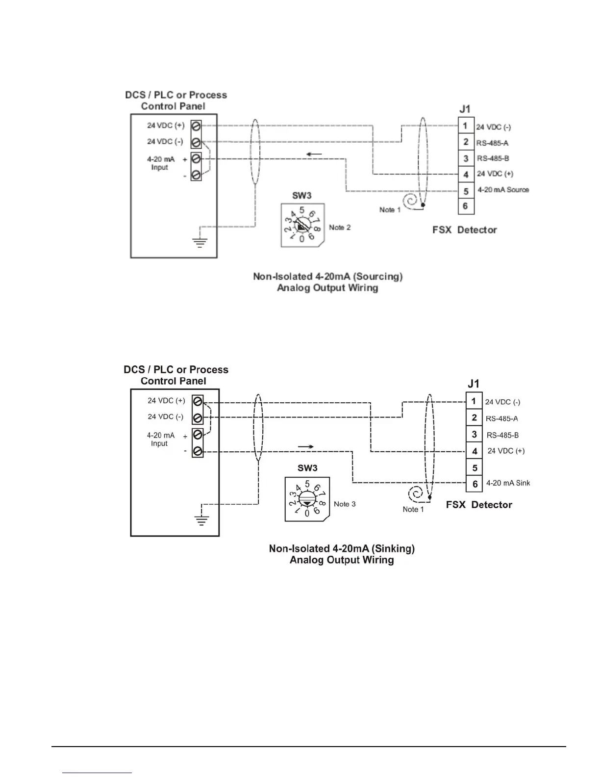
Figure 4-5
Typical Wiring for 4-20mA (Sourcing) Analog Output
Figure 4-6
Typical Wiring for 4-20mA (Sinking) Analog Output
NOTES:
1. Cable shield must be grounded at one end only, at the Control Panel. Coil and tape cable shield
at the Detector end.
2. Set SW3 (rotary switch) to position one (1) for Source current wiring.
3. Set SW3 (rotary switch) to position zero (0) for Sink current wiring.

Other manuals for Honeywell FS24X

Questions and Answers:

Question and Answer IconNeed help?

Do you have a question about the Honeywell FS24X and is the answer not in the manual?

Honeywell FS24X Specifications

General IconGeneral
BrandHoneywell
ModelFS24X
CategorySecurity Sensors
LanguageEnglish

Related product manuals