Installation Guide and Operating Manual
Honeywell 19
3.6 Fault Conditions
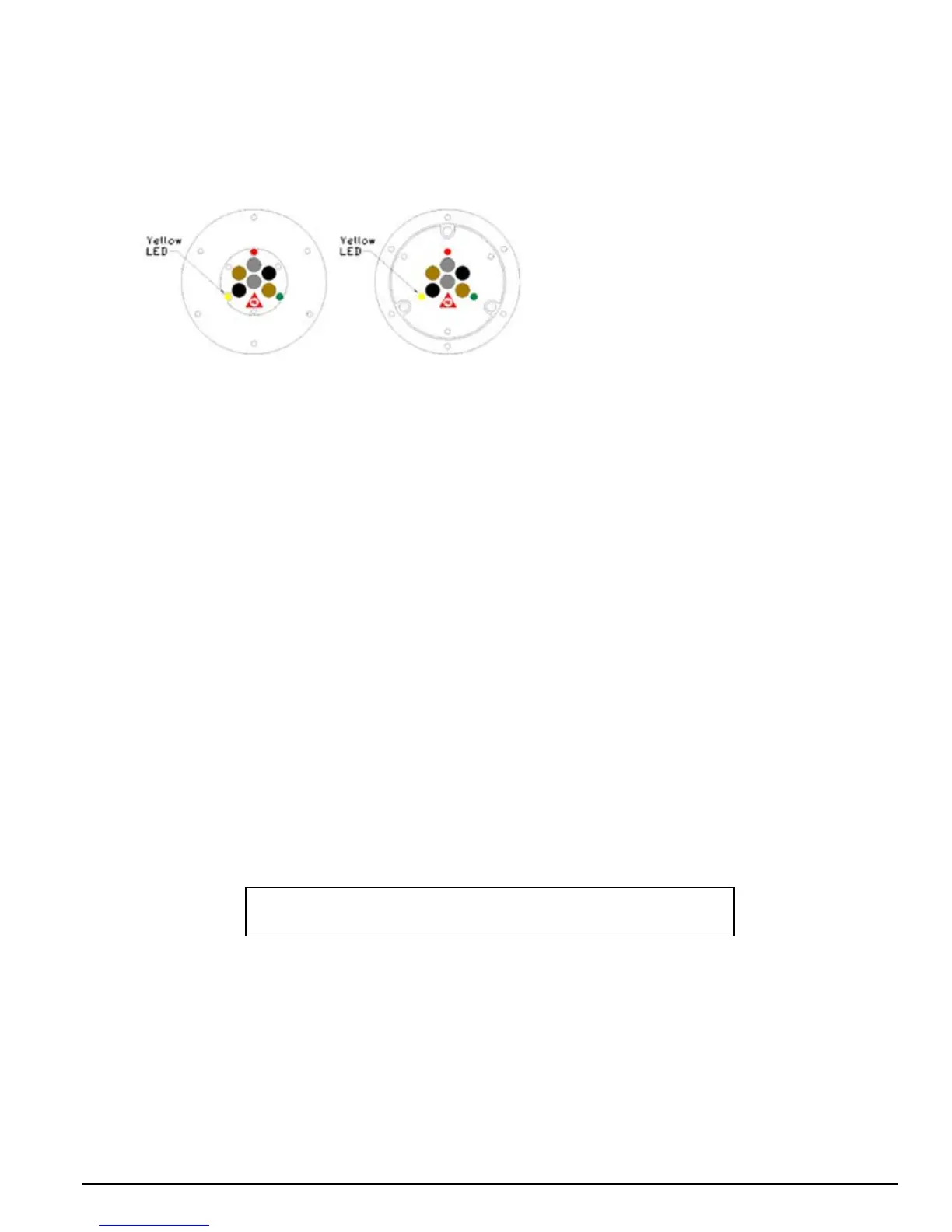
When a Fault (Trouble) condition occurs, the Yellow LED will illuminate. See Figure 3-6 for the location of
the Yellow LED.
The Detector has the following outputs with a
Fault condition:
Fault Relay activation
4-20 mA (
sink) Output
3
2 mA (Dirty Window Fault)
0 mA (All Other Faults)
4-20 mA (
source) Output
3
2 mA (Dirty Window Fault)
0 mA (All Other Faults)
RS-485 FireBus
II Fault Notification
3
RS-485 Modbus Fault Notification
3
3 Only One Active Fault output from this group
Figure 3-6
Detector Module, Front View
Fault (Trouble) conditions can be caused by:
Under Voltage Input Power (< 18 VDC).
Over Voltage Input Power (> 32 VDC).
Over Temperature (> 85° C or 185° F for the Standard Version).
Under Temperature (< -40° C or -40° F for the Standard Version).
One or more Microprocessor Failures.
One or more Relay Coil Failures.
Communication Fault.
Electronic Self-Test Failure.
Dirty Window Lens (Yellow LED flashes, the Yellow LED is ON [solid] for all other Faults).
3.7 Maintenance
After the FS24X Detector is installed and commissioned, there is little maintenance required. However, a
complete “end-to-end” test of the entire fire detection system should be performed periodically depending on
the application. Additionally, semi-annual or quarterly testing should be performed, using the correct
Honeywell Analytics Test Lamp, to ensure the integrity of the entire fire protection system.
In order to ensure the Detector is operating properly at all times, it may be necessary to establish a periodic
cleaning schedule. Some industrial environments may necessitate more frequent cleaning of the Detector’s
optical surfaces than others.
WARNING – Potential electrostatic charge, wipe enclosure only
with a damp cloth
 Loading...


