Description
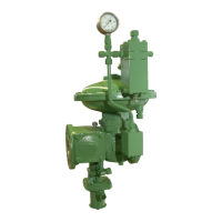
HON 380 gas pressure regulator with HON 673/674 controller 13
Design of the regulator unit:
Figure No. Meaning
1 Spring adjuster
2 Pilot spring
3 GPR vent line connection
4 GPR comparator diaphragm
5 GPR measuring line connection
6 Compensating diaphragm
7 Valve spindle
8 Valve plate
The design of the controller is described in the component documentation in-
cluded in delivery.
Connections of the gas pressure regulator:
Figure No. Connection
1 Vent line connection, regulator unit
2 Measuring line connection, regulator
unit
3 Measuring line connection, SAV
4 Vent line connection, SAV
unit RE0
controller
the HON 380 gas
pressure regulator
 Loading...