Description
HON 380 gas pressure regulator with HON 673/674 controller 9
Control range W
dsu
Design for lower response pressure
5 to 60 mbar
K4: Diaphragm measuring unit
15 to 120 mbar
K5: Diaphragm measuring unit
40 to 300 mbar
K6: Diaphragm measuring unit
The technical specifications and the Maintenance section, as well as the spare
parts lists and spare parts drawings in the appendix, describe all the gas pressure
regulator versions and all the models corresponding to the standard for this de-
vice type. Special-purpose versions are identified with “SO” in the inspection cer-
tificate, which is included with the gas pressure regulator.
However, other versions and models will be covered specifically as well when there
are important differences that need to be pointed out.
If you have trouble understanding the information in this documentation, contact
the manufacturer without fail before starting any work on the device.
2.3 Labels/Markings
Illegible information on the device poses a risk of injury due to resulting erro-
neous operation, use, or installation.
Labels, as well as inscriptions and stamping on the device, can eventually be-
come soiled or otherwise unrecognizable to such an extent that users will not be
warned effectively of hazards and may be unable to follow required operating in-
structions. This will pose a risk of injury.
Make sure to always keep all relevant labels in good condition so that they will
be easily legible.
Immediately replace damaged and missing labels.
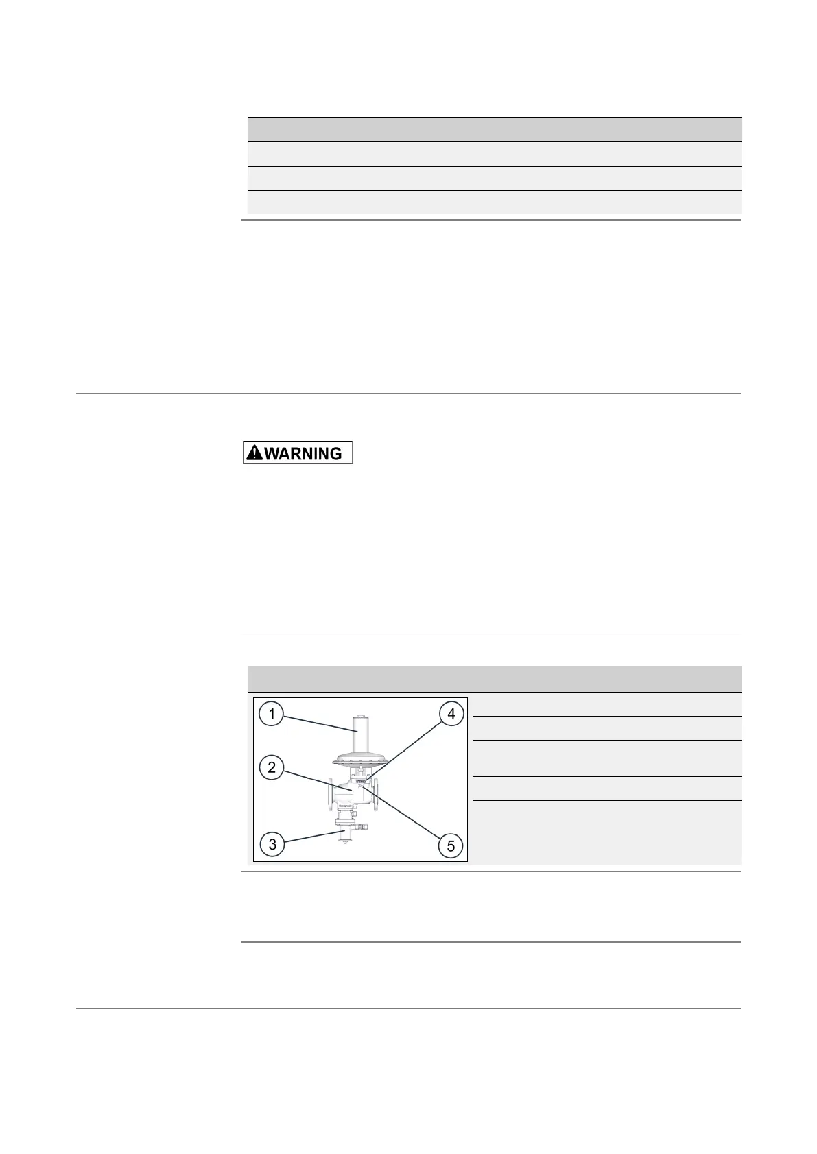
The labels and markings of the gas pressure regulator can be found here:
Figure No. Description
1 Regulator type plate
2 Gas pressure regulator type plate
3 Arrow indicating direction of flow on
controller type plate
4 Body nominal size
5 Arrow indicating the direction of flow
For the location of the nameplates, as well as a detailed list of the information on
them and what it means, please refer to:
Identifying the device (see page 10)
Small labels must be used to color-code and explicitly name the gas pressure reg-
ulator’s connection lines (measuring lines and operating lines) based on what the
lines are intended for and their minimum nominal size.
Versions and designs
in this user manual
tor HON 380 labels
and markings
Nameplates
lines
 Loading...