Transport and installation
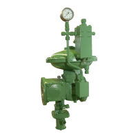
HON 380 gas pressure regulator with HON 673/674 controller 32
The test setup is as follows (schematic diagram, using the RE1 DN50 and
HON 673 as a reference):
The numbers have the following meaning:
No. Meaning
1 Inlet chamber
2 Outlet chamber
3
Inlet stop valve armature
4
Outlet stop valve armature
Proceed as follows:
Step Description
1 Slowly close the outlet stop valve armature.
2 Apply the test medium to all detachable pipe joints.
3 Observe the test medium on all detachable pipe joints for several minutes.
If … then …
no foam or bubbles are formed
the system is leak-proof.
the system may be put into operation.
foam or bubbles are formed
the affected pipe joint is leaking.
the system may not be put into operation.
Proceed with step 4.
Step Description
4 Slowly close the inlet stop valve armature.
5 Depressurize the inlet chamber and the outlet chamber.
6 Seal the leaking pipe joints.
7 Repeat the leak test starting with step 1.
for leaks
 Loading...