01.
Install a 10K resistor between the communicator ground and its each input.
02.
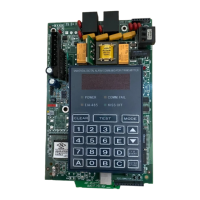
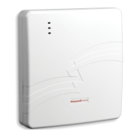
Connect the panel relay terminals and the communicator as specified in Wiring for Dry Contact Relay Monitoring.
03.
Power up the system as specified in Powering On.
Figure 5-1: Wiring for Dry Contact Relay Monitoring
NOTE: Note : To connect with Normally Closed (NC), the wiring will remain same as shown in the diagram above.
Make sure you have connected a 10K resistor between the Input and Common (C) both for Normally Open (NO) and Normally
Closed (NC) setup.
If it is connected to Normally Closed, a template change is required to be made in CLSS site manager.
5.8 POWERING ON
01.
Power ON the communicator and the panel.
02.
Ensure that the panel and the communicator are receiving power.
Honeywell Connected Life Safety Services | Honeywell Connected Life Safety Services
Installation and Operation Manual | REV. B
18
Wednesday, February 28, 2024
 Loading...
