Fire Alarm Control Panel IQ8Control C/M
26 FB 798951.GB0 / 01.09
4 Module
The FACP IQ8Control C / M has a modular design so that modules can be replaced/extended at any time.
Only remove or insert modules when the FACP is voltage free.
Switch off the power and battery supply.
Wait for at least 10 seconds before the modules are replaced or supplemented.
Take suitable measures to discharge static electricity.
Check correct installation (modules and connection cables).
Switch on the power and battery supply.
If necessary, check/supplement the customer data using the programming software tools
8000.
4.1 Power supply module (Part No. 802426 index G or higher)
The power supply module is installed on the Basic module of the FACP. This module accommodates the entire
voltage supply for the Fire Alarm Control Panel and the +12 V DC supply voltage for external devices. Maximum
current load from external users will depend on control panel configuration. If necessary, additional supply is
possible from a monitored external power supply unit. The power supply module is suited to connect 2 batteries
(2 x 12 V / 24 Ah). In case of an AC power (230 V DC) loss the panel operation will be supplied without
discontinuation (refer chapter 4.1.3).
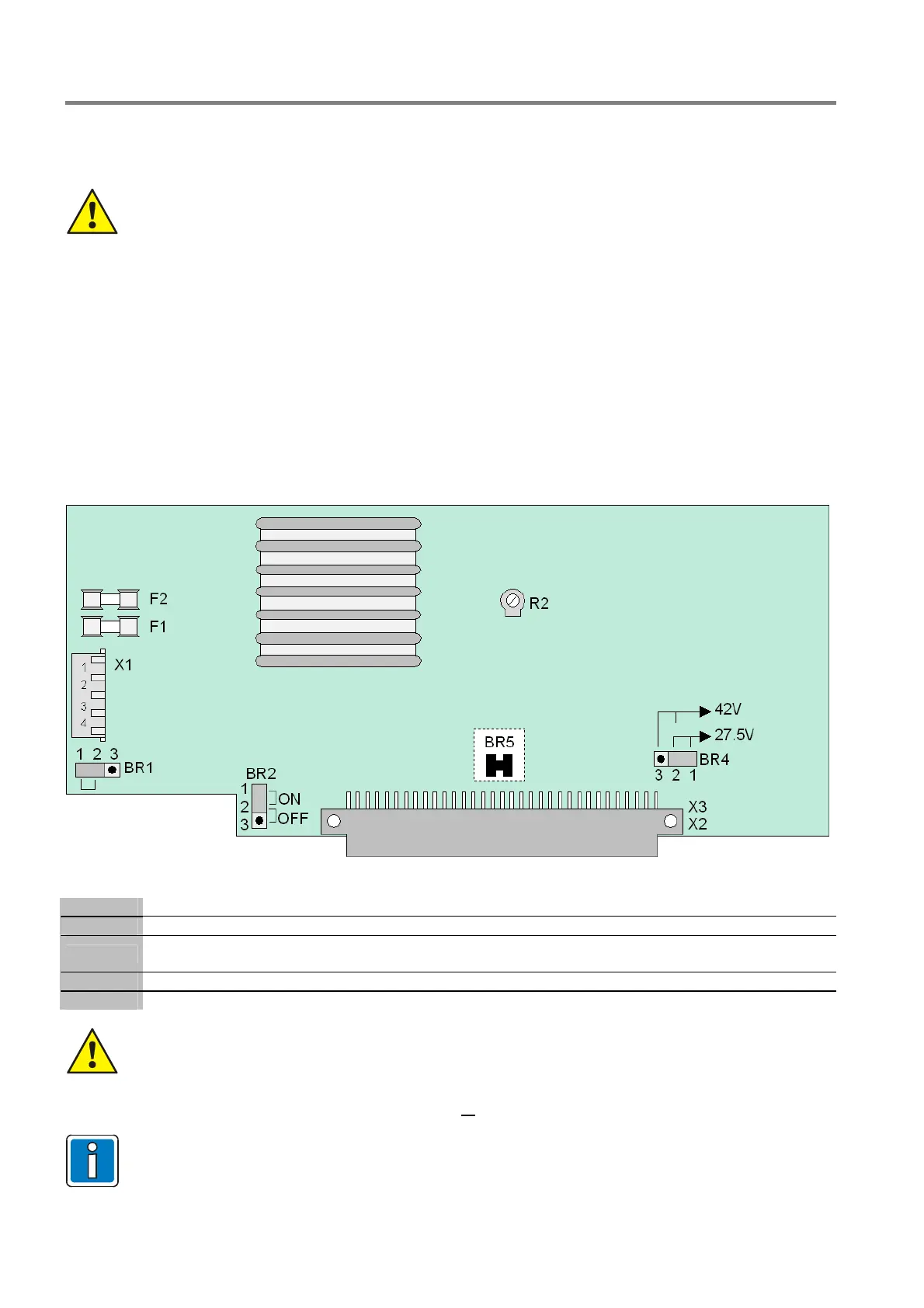
Fig. 21: Power supply module (Part No. 802426 from index G)
X1
Plug connector for transformer (secondary)
X 2/3
Basic module connector
F1
Fuse for the FACP internal power supply: T 4 A
to the analog loop 27,5 V (esserbus
®
) or 42 V (esserbus
®
PLus)
F2
Fuse for secondary side: T 5 A
R 2
Potentiometer for adjusting the battery charging voltage to +13.65 V DC (@ 25 °C)
The power supply module must only be installed or removed with the Fire Alarm Control Panel in a
de-energised state.
When you are installing or replacing the power supply module, observe the BR5 solder
bridge/jumper (on the rear side of the circuit board). This jumper is used to set whether the power
supply unit is installed in an FACP 8000C/M or
an IQ8Control C/M. If the jumper is set incorrectly,
this could damage the Fire Alarm Control Panel or the power supply unit.
The battery charging voltage is set to the abovementioned values by the manufacturer. If the FACP
is used at other ambient temperatures (refer to technical data), then the battery charging voltage
must be adjusted accordingly using potentiometer R2.

 Loading...


