Fire Alarm Control Panel IQ8Control C/M
FB 798951.GB0 / 01.09 55
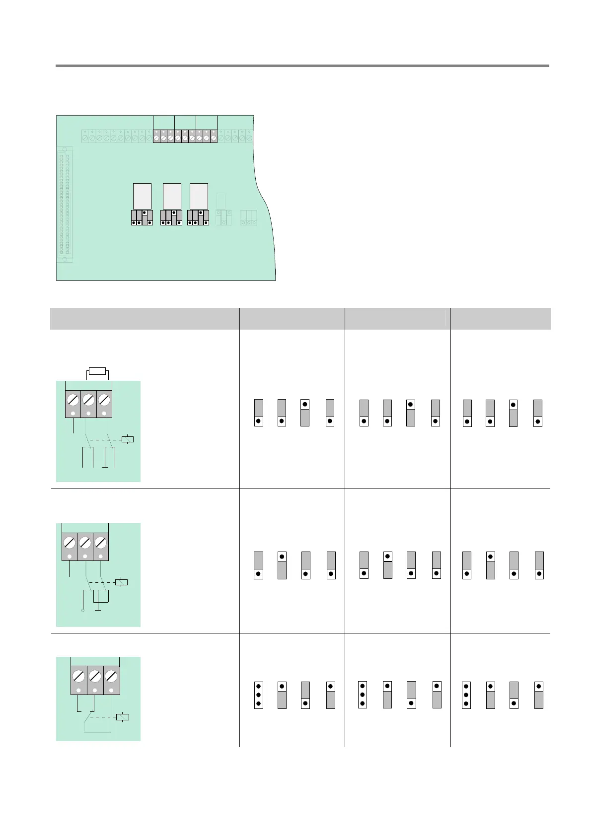
4.3.9 Connecting the Relays K2, K3, K4
Location of the relay K2,K3,K4 and the jumpers BR9 to 20 on the Field device module
BR19
BR18
BR17
BR15
BR14
BR13
BR11
BR10
BR 9
K4 K3 K2
BR12
BR16
BR20
K3K4 K2
1
2
3
1
2
3
1
2
3
CNCNO CNCNO CNCNO
Jumpers are used for adjusting the three relays K2, K3
and K4 to a variety of requirements.
The three relays may be coded independently of each
other as >positive-switching< and >monitored, positive-
switching< or as >potential-free change-over contact<.
Fig.50: Connecting the Relays K2,K3,K4
K2 K3 K4 Relay
Positive switching / monitored
CNC
NO
+
K
10 K
R *
n. c.
+12V DC
Ub int.
UMess
Signale in operation
+
-
monitoring
BR 9BR 10BR 11
1
2
3
BR 12
1
2
3
1
2
3
1
2
3
BR 13BR 14BR 15BR 16
1
2
3
1
2
3
1
2
3
1
2
3
BR 17BR 18BR 19BR 20
1
2
3
1
2
3
1
2
3
1
2
3
Positive switching / not monitored
+12V DC
Ub int.
K
+
-
n. c.
CNC
NO
BR 9BR 10BR 11BR 12
1
2
3
1
2
3
1
2
3
1
2
3
BR 13BR 14BR 15BR 16
1
2
3
1
2
3
1
2
3
1
2
3
BR 17BR 18BR 19BR 20
1
2
3
1
2
3
1
2
3
1
2
3
Change-over contact / not monitored
K
CNC
NO
BR 9BR 10BR 11BR 12
1
2
3
1
2
3
1
2
3
1
2
3
BR 13BR 14BR 15BR 16
1
2
3
1
2
3
1
2
3
1
2
3
BR 17BR 18BR 19BR 20
1
2
3
1
2
3
1
2
3
1
2
3

 Loading...


