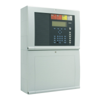
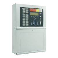
Fire Alarm Control Panel IQ8Control C/M
FB 798951.GB0 / 01.09
3
1
Installation Instruction................................................................................................................................................. 5
2 System overview........................................................................................................................................................ 7
3 Configuration options................................................................................................................................................. 8
3.1 Special configuration – Swiss option
CH
......................................................................................................... 9
3.2 FACP IQ8Control C........................................................................................................................................... 10
3.3 FACP IQ8Control M........................................................................................................................................... 12
3.4 Definition of the Primary loop number.............................................................................................................. 17
3.5 Central housing.................................................................................................................................................. 19
3.6 Assembly............................................................................................................................................................ 20
3.7 Cable glands ...................................................................................................................................................... 25
3.8 Panel buzzer ...................................................................................................................................................... 25
4 Module ...................................................................................................................................................................... 26
4.1 Power supply module (Part No. 802426 index G or higher)........................................................................... 26
4.1.1 Mains connection and earth connections .................................................................................... 28
4.1.2 Protective and Functional earth................................................................................................... 29
4.1.3 Emergency power supply ............................................................................................................ 30
4.1.4 Specification Power supply module (Part No. 802426) ............................................................... 33
4.2 Basic module...................................................................................................................................................... 34
4.3 Software.............................................................................................................................................................. 37
4.3.1 Firmware Update ......................................................................................................................... 37
4.3.2 Customer data programming.......................................................................................................39
4.3.3 Housing contact ........................................................................................................................... 40
4.3.4 Serial interface............................................................................................................................. 41
4.3.5 Micro module slot......................................................................................................................... 44
4.3.6 Technical data Basic module....................................................................................................... 45
4.3.7 Connecting a fire department operating panel ............................................................................ 50
4.3.8 Connecting the master box (Relay K1)........................................................................................ 51
4.3.9 Connecting the Relays K2, K3, K4 .............................................................................................. 55
4.3.10 Technical data Field device module .................................................................................... 57
4.4 Extension module .............................................................................................................................................. 58
4.4.1 Technical Data Extension module ............................................................................................... 59
5 Micro module............................................................................................................................................................ 62
5.1 Analog loop modules......................................................................................................................................... 62
5.1.1 esserbus
®
Analog loop module (Part No. 784382 / 784382.10 / 784382.D0) ............................. 64
5.1.2 esserbus
®
-PLus Analog loop module (Part No. 804382 / 804382.10 / 804382.D0) ................... 65
5.1.3 Technical Data Analog loop module............................................................................................ 68
5.2 essernet
®
module............................................................................................................................................... 69
5.2.1 essernet
®
micro module (Part No. 784840 / 784840.10 and 784841 / 784841.10) .................... 70
5.2.2 Technical data essernet
®
micro module ...................................................................................... 72
6 Relay module............................................................................................................................................................ 76
6.1 3-relay module / 3-relay common trouble module........................................................................................... 76
6.2 4- Relay module................................................................................................................................................. 81
6.2.1 Technical Data Relay module...................................................................................................... 83
6.3 Serial interface module...................................................................................................................................... 84
6.3.1 RS 232 / TTY module .................................................................................................................. 84
6.3.2 Technical data interface modules................................................................................................86
 Loading...
