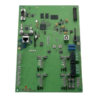
EMM-3U UNIVERSAL ELECTRONIC MINIZONE™ PANEL
11 68-0237-2
Fig. 19. EMM-3U with Air Conditioning Zoned with Dampers and Hydronic Heat Using V8043 Zone Valves.
STARTUP AND CHECKOUT
After the installation is complete, verify correct operation:
1. Place the Em Ht switch in the Off (down) position.
2. Verify that DIP switches are set correctly.
3. Turn on power to the EMM-3U Panel and set the ther-
mostats so no zones are calling.
a. EMM-3U enters the Purge Mode, opening all damp-
ers and operating the fan for two or three and one-
half minutes (configurable). In Purge, damper LEDs
are green to indicate the dampers are open.
NOTE: If a Discharge Air Temperature Sensor is not con-
nected to the panel, the purge LED flashes in all
modes other than Purge.
b. Press the Purge Override button on the panel to exit
the Purge mode early.
4. Set the zone one thermostat to heat and raise the set-
point to call for heat.
5. Verify that the heat LED is red and the zone one damper
remains green while the other damper LEDs turn off.
6. Raise zone two setpoint to call for heat. Lower zone one
setpoint to stop the call for heat to that zone.
7. Verify that zone one LED turns off and zone two LED
turns green.
8. Repeat for zones two and three.
9. Alternately, set the System switch to Cool, and lower the
setpoint to call for cooling.
10. Verify that the green cool LED illuminates.
OPERATION
Identifying DIP Switches
This panel has one bank of 12 DIP switches numbered
starting with 1 on the left. The switches are shipped in the On
(Up) position. See Fig. 13 and Tables 4 and 5.
ZONE DAMPER MOTORS
M1 - common
M4 - power open
M6 - power closed
24 Volt Equipment
MOMENTARY PUSHBUTTON SWITCHES:
BOOT USED TO CLEAR THE SYSTEM AND MICROPROCESSOR.
PURGE OVERRIDE USED TO BYPASS THE PURGE CYCLE WHILE TROUBLESHOOTING.
DIP Switches (see Installation Instructions for details):
1, 2, 3: Set to off for 1 stage heat and cool
4: Set to on for conventional equipment
5: Set to on for 160°F high limit
6: Set to on for 40°F or off for 48°F
7: Set to on
8: Set to on for no purge fan after call for heat or cool
9: Set to on
10: Set to on
11: Set to on
12: Set to on
R
C
R
H
W
1
W
2
E
BOOT PURGE
OVERRIDE
1 Leave this jumper
disconnected.
Discharge Air
Temperature
Sensor
(See C7735
Installation
Instructions
for further
information.)
R
C
DATS
DATS
OFF
ON
EM
HEAT
B
O
Y
1
Y
2
G
R on Fan Center for AC
Compressor Relay
Fan Relay
his diagram shows the typical
ir conditioning system and
ydronic zone valve hookup
sing common dampers and
ingle stage thermostats.
or specific instructions, refer
o Installation Instructions.
456Z
123X
Power-open
Power-closed
(Opposed Blade
Damper Motors)
G W2Y2 M6M4M1
G
Y1
YW
C
Rc
R
Rh RcRh RcRh
L
Zone 1 Thermostat
V8043E
Yellow Leads
ZONE 3
G W2Y2 M6M4M1
G
Y1
YW
CRL
Zone 2 Thermostat
ZONE 2
G W2Y2 M6M4M1
G
Y1
YW
CRL
Zone 3 Thermostat
ZONE 1
CR
Power-closed
Spring-open
(Model ZD)
Power-closed
Spring-open
(Model ARD)
24 Volt 40 VAC
Transformer
24 VAC
40VA
R
C
/R
H
JUMPER
ZONE PANEL
TRANSFORMER
HEAT COOL PURGE FAN EM. HEAT ZONE 1 ZONE 2 ZONE 3
EQUIPMENT
1
O
N
2 3 4 5 6 7 8 9 101112
111
O/BW1/E O/BW1/E O/BW1/E
V8043F V8043F
Th/Tr
Th
Th/Tr
Th
 Loading...

