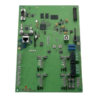
EMM-3U UNIVERSAL ELECTRONIC MINIZONE™ PANEL
68-0237-2 8
Hot Water Heat Systems
Hydronic Heat
Hydronic heat systems using zone valves or circulator relays
for heating and dampers for cooling can be controlled by the
panel. In this hookup, one thermostat is used per zone to
control both heating and cooling. Use thermostats with
separate Rc and Rh terminals to isolate the heating and
cooling circuits. Connect the thermostat Rh and W to the zone
valve and the Rc, Y and G to the zone control panel. Wire the
thermostats and air conditioning equipment the same as for
conventional equipment; see Fig. 3 and 16.
Hydro Heat
Hydro heat systems using a boiler and hot water coil can be
used with this zone control panel. Wire the zone valve or
circulator relay to equipment terminals Rh and W. The Rc and
Rh jumpers located above the equipment terminals must be
removed if a separate transformer powers the heating and
cooling circuits. Wire the cooling equipment, thermostats, and
dampers the same as for conventional equipment; see Figure
19. Set DIP switch 7 to off if it is necessary for the fan to be
energized on a call for heat. Alternatively, an Aquastat can be
used to engage the blower based on water temperature.
Heat Pump Equipment
See Fig. 17 and 18 for heat pump equipment wiring. Refer to
the manufacturer instructions for additional wiring details and
substitute the EMM-3U equipment terminals for the
thermostat terminals shown.
If the same heat source is used for auxiliary heat and
emergency heat:
• Connect the auxiliary heat to W2.
• Wire a jumper from W2 to E.
• Set DIP switch 12 to Off.
If auxiliary heat is separate from emergency heat:
• Connect the auxiliary heat to W2.
• Connect the emergency heat to E.
• Leave DIP switch 12 set to On.
Connect the changeover relay to the O or B equipment
terminal (O is energized when the panel is in the cool mode, B
is energized when the panel is in the heat mode).
IMPORTANT
Some heat pump manufacturers (such as York and
Trane) use the B terminal as the transformer com-
mon. Do not connect the common from the equip-
ment to the zone control panel.
Connect the compressor wire to the Y1 terminal. If there is a
2
nd
stage compressor, wire it to Y2 with a jumper to W2.
To control a two-stage heat pump with auxiliary heat, select
the TZ-4 TotalZone Zone Control panel.
Set DIP switch 4 to Off for heat pump operation, and set DIP
switch 7 to Off for fan on a call for heat.
See the Operation section for additional configuration
settings.
Transformer
Wire a dedicated transformer to the R (hot) and C (common)
terminals on the zone control panel as shown in Fig.13. One
40 VA, 24 Vac transformer powers up to five ARD or ZD
Dampers and the panel.
 Loading...

