EMM-3U UNIVERSAL ELECTRONIC MINIZONE™ PANEL
68-0237-2 4
INSTALLATION
Mounting
CAUTION
Equipment Damage Hazard.
Do not mount EMM-3U inside HVAC equipment.
Mount only on wall or on cold air return.
1. Mount the thermostats in each zone of the living space
using the installation instructions provided with each
thermostat.
2. Mount the dampers in the ductwork using the installa-
tion instructions provided with each damper.
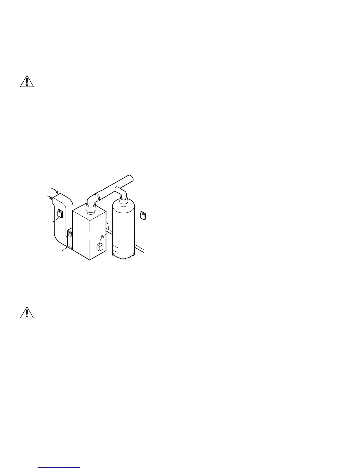
3. Mount the EMM-3U zone panel near the HVAC equip-
ment; locate it on a wall or on the cold-air return. See
Fig. 2.
4. Level the EMM-3U for appearance only.
Fig. 2. EMM-3U mounting location.
WIRING
CAUTION
Voltage Hazard.
Can cause electrical shock or equipment damage.
Disconnect power before continuing installation.
Wiring must comply with applicable codes, ordinances and
regulations.
1. Connect thermostats as shown in Fig. 3-7.
2. Connect dampers as shown in Fig. 8-12.
3. Connect C7735A1000 Discharge Air Temperature Sen-
sor (DATS) to the DATS terminals. The wires are not
polarized; see Fig. 13.
4. Connect the HVAC equipment to the EQUIP terminals
on the panel; see Fig. 13-18.
5. Connect a 40 VA, 24 Vac transformer to R (hot) and C
(common). This must be a dedicated transformer. See
Fig. 13.
Thermostat Wiring
Conventional Equipment
Conventional (RWYG) thermostats can be used to control
conventional, multi-stage and heat pump equipment. When
single-stage thermostats are used, stages are engaged
through the on-board 5 - 60 minute timer. If the equipment is a
heat pump, the EMM-3U panel controls the reversing valve. If
the thermostat has a common terminal, it is wired to C on the
panel, see Fig. 3. Multi-stage conventional (non-heat pump)
thermostats are wired with the second stage of heat and cool
on the thermostat to W2 and Y2 on the panel. Leave the O/B
thermostat jumper on the EMM-3U disconnected.
The PC8900 can be used as a zone thermostat. See Fig. 4 for
hookup. The PC8900 with the W8900A or C controls up to 2
heat and 2 cool stages of conventional equipment. The
PC8900 with the W8900A also controls heat pump
equipment.
Connect a jumper on the W8900 from Rc to Rh as shown.
Wire terminals R and C to a transformer. Alternately, if the
zone control system current draw is within specifications, the
R and C on the W8900 could be connected to R and C on the
EMM-3U. The PC8900/W8900 draws 5 VA.
Heat Pump Equipment
Select a heat pump thermostat from Table 1. If the thermostat
selected has a separate Y1 and W1 wire, connect as shown in
Fig. 5, leaving the zone O/B thermostat type jumper on the
EMM-3U disconnected
If the PC8900/W8900A is used, wire as shown in Fig. 4. This
hookup engages second stage heat based on thermostat
demand, but the Em Heat switch on the panel must be used to
switch the panel to emergency heat.
NOTE: The thermostat Em Heat switch does not switch the
panel to emergency heat.
If the thermostat selected from Table 1 has a single Y terminal
for first stage heat and cool, wire as shown in Fig. 6 and 7.
Wire either O or B (not both) from the thermostat to the O/B
terminal on the EMM-3U. Locate the O/B thermostat jumper
on the EMM-3U near each zone thermostat wiring terminal.
Connect the jumper if O is used or leave the jumper
disconnected if B is used. Connect second stage, auxiliary
heat, to W2.
Conventional single stage thermostats can be used to control
a heat pump if wired as shown in Fig. 3. In this case, the panel
operates the reversing valve, the second stage is brought on
by the panel stage timer, and emergency heat is activated by
the EM heat switch on the panel. Leave the O/B thermostat
type jumper disconnected when using conventional
thermostats.
M14762
WATER
HEATER
EMM-3
E
L
E
C
T
RO
NI
C
A
I
R CLEANER
RETURN
AIR
EMM-U3
PTIONAL
OCATION
FURNACE
OR BOILER
HIGH
EFFICIENCY
AIR CLEANER

 Loading...


