EMM-3U UNIVERSAL ELECTRONIC MINIZONE™ PANEL
7 68-0237-2
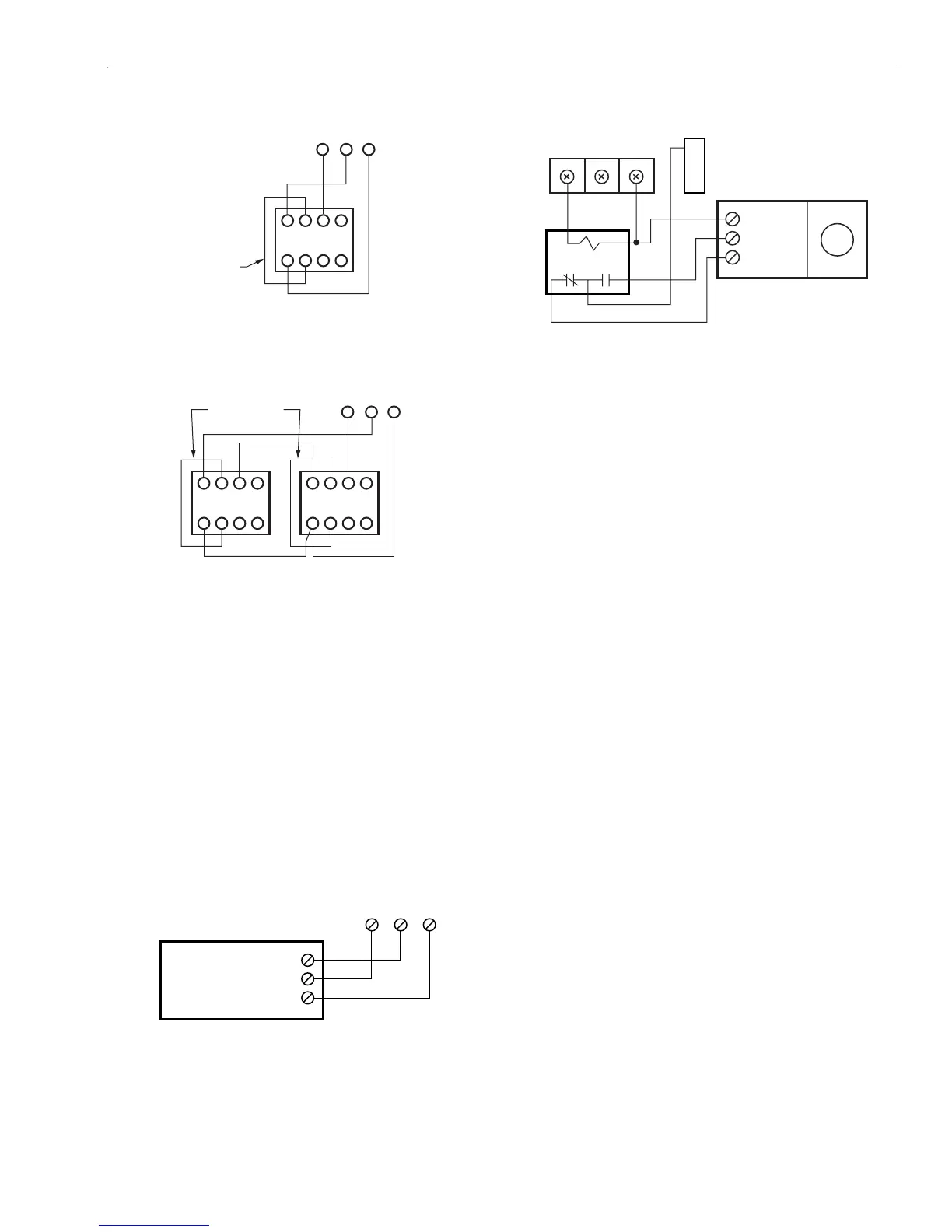
Fig. 9. Wiring AOBD Damper to panel.
Fig. 10. Wiring two AOBD dampers in parallel.
MARD Dampers or Dampers Using ML6161 Motor
Actuator
Wire the MARD Damper or ML6161 Actuator to the panel as
shown in Fig. 11. These are floating control actuators, but are
controlled as two-position devices on the EMM-3U Panel.
Multiple dampers can be wired in tandem.
The ML6161 Motor causes the damper LED to illuminate
green constantly. Wire a relay as shown in Fig. 12 to restore
damper position indication.
Use the MARD or D642 Damper with the ML6161 on systems
2000 cfm and higher.
Fig. 11. Wiring MARD Damper or ML6161 Actuator to
panel.
Fig. 12. MARD or ML6161 Damper Motor Actuator using
R8222 Relay wiring.
Discharge Air Sensor Wiring
Wire the C7735 Discharge Air Temperature Sensor (DATS) to
the panel as shown in Fig. 13 -16.
The Purge LED (amber) flashes in all modes except purge if:
1. No DATS is connected to the EMM-3U.
2. There is a problem with the DATS sensor.
3. There is a problem with the DATS wiring.
The zone control panel will continue to operate correctly when
the purge LED is flashing but without the high and low limit
protection.
Equipment Wiring
Conventional Equipment
Wire the heating and cooling equipment to the equipment
terminals on the EMM-3U Panel as shown in Fig. 17.
Conventional Equipment: Leave DIP switch 4 set to On.
Electric Furnace: Set DIP switch 7 to Off to energize the fan
with a call for heat.
Oil Heat: Wire the oil primary T, T terminals to the Rh and W
equipment terminals. (If the oil primary has powered
terminals, remove the Rh and Rc jumper.) See Fig 15 and 16.
Multi-Stage: Wire the equipment as shown in Fig. 13 using the
W2 for second stage heating, and the Y2 for second stage
cooling.
See the Operation section for stage configuration and other
settings.
4
M6 M4 M1
5 6
123
Z
X
DAMPER MOTOR
IELD JUMPER
M1906
MOTOR TERMINALS
4
M6 M4 M1
5 6
123
DAMPER MOTORS
M1906
MOTOR TERMINAL
4 5 6
123
Z
X
Z
X
FIELD JUMPER
M1 M4
M20136A
ZONE PANEL
CONNECTION
M
CW
COM
CCW
MARD
COM
CCW
CW
ML6161
R8222 RELAY
ZONE CONTROL PANEL
DAMPER TERMINALS
M20548
M6 M4 M1
R
C

 Loading...


