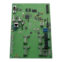
EMM-3U UNIVERSAL ELECTRONIC MINIZONE™ PANEL
68-0237-2 12
Sequence of Operation
• When there is no call for heat, cool, or fan, the EMM-3U is
in the Idle mode. No system LEDs are illuminated and the
damper LEDs are green to indicate open.
• On a call for heat, cool, or fan, the calling zone damper
stays open, and the other zone dampers close:
— Panel energizes the HVAC equipment and conditioned
air is delivered to the calling zone.
— Heat LED (red), cool LED (green), or fan LED (green)
illuminates to indicate equipment operation.
— Fan LED illuminates only during a call for circulation; it
does not illuminate during a call for heat or cool.
• When the call is satisfied, the system enters the Purge
mode. After Purge, all dampers return to the Open position
• Any zone thermostat can call for heating or cooling. If there
are co-existing calls for heat and cool, the panel accepts
the first call.
• Once a call is satisfied, or a maximum of 20 minutes has
elapsed, the panel switches to allow the opposite call after
completing Purge mode.
Purge Mode
• At the end of every call for heat or cool, the panel enters a
Purge mode that holds open the calling zone damper for
two minutes (default) or three and one-half minutes.During
this time, the panel or the HVAC equipment can be
configured to operate the fan.
• The Purge LED lights to signal that the system is in the
Purge mode. Pressing the purge override button overrides
the Purge mode.
• Unless there is a new call for heat or cool during the Purge
mode, all dampers are moved to the Open position at the
end of Purge.
• The panel can be configured to open all dampers during
purge mode.See Table 4 to configure the Purge mode
using DIP switches 8, 9 and 10.
Individual Zone Fan Control
• The fan switch of each thermostat controls the fan
operation for that zone.
• When the Fan switch is in the On position, the fan is
energized, and dampers close to zones where the Fan
switch is in Auto position.
• During a call for heat or cool at this time, the circulation
mode ceases, and the heat or cool call is honored.
• When the zone calling is satisfied, the circulation call
resumes.
Single- and Multi-Stage Operation
The panel can control up to two stages of heat and cool:
• First stage is energized by the thermostat
• Second stage of heating or cooling can be energized by
the thermostat or timer.
Single-Stage
Select a single stage thermostat, see Table 1. Set DIP
switches 1, 2, and 3 to Off to disable the stage timer.
Multi-Stage
THERMOSTAT-CONTROLLED STAGES
• Select a multi-stage thermostat, see Table 1, that
energizes W2 and Y2 for second stage of heat and cool.
• Configure DIP switches 1, 2 and 3 to Off to disable the
stage timer.
Timer Controlled Stages
• The panel stage timer energizes the second stage of heat
or cool after the first stage has been calling for a specified
amount of time.
• Second stage remains energized until the call for heat or
cool is satisfied.
• See Table 5 for stage timer configuration.
Heat Pump Operation
The panel can control single or two stage heat pumps with or
without auxiliary heat:
• Set DIP switch 4 to Off for heat pump control. This
energizes the Y1 on a call for first stage heat or cool.
• Set DIP switch 7 to Off to engage the fan with a call for
heat.
Thermostat Controlled Stages
• Select a thermostat from Table 1. Configure DIP switches
1,2, and 3 to off to disable the stage timer.
— When thermostat calls for first stage, panel energizes
Y1, G and the correct reversing valve terminal.
— When the thermostat calls for second stage heat on
W2, the panel energizes the equipment W2 terminal.
• Recommended heat pump thermostats can switch the
panel to emergency heat:
— In this mode, Y1 equipment terminal is disabled and E
is energized on a call for heat.
— If the same source of heat is used for emergency heat
and auxiliary heat, W2 and E equipment terminals
must be jumpered.
• Emergency heat can be energized by the Em Heat switch
on the panel.
• If the equipment is a two-stage heat pump, W2 and Y2
equipment terminals must be jumpered and wired to the
second stage compressor contactor.
• If the equipment is a two-stage heat pump with auxiliary
heat, select the TZ-4 TotalZone™ panel.
Timer Controlled Stages
If single-stage thermostats are used, the EMM-3U can
energize second stage using stage time:
• The timer can be set to engage second stage heat or cool
after the first stage has been calling for the specified length
of time.
• See Table 5 for DIP switch configuration.
Thermostat Operation
Conventional Thermostats
Conventional (R,W,Y,G) heat/cool thermostats can be used
with the EMM-3U to control single or multi-stage gas, electric,
or oil systems and heat pumps with or without auxiliary heat.
• For two stage heat or cool equipment, configure the stage
timer with DIP switches 1, 2 and 3. See Table 5. This
enables the panel to engage second stage after stage one
has been calling for the specified length of time.
 Loading...

