22 AMPS-24 Manual — P/N 51907:J2 02/26/2014
Installation Wiring the AMPS-24/E
• DVC Series
•NCM-W/F
• DS-DB Digital Series board (+/- 485 terminals must be connected).
Figure 2.11 Connecting to the Main 24 Output TB1, Example 2
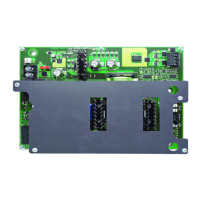
Figure 2.12 is a block diagram representing an application where an AMPS-24 is used as a general
purpose remote power supply and battery charger.
Figure 2.12 AMPS-24 as Battery Charger/General Purpose Remote Power Supply
+24V
+24V
COM
COM
+24V
+24V
COM +485
- 485
COM
TB1
MAIN 24V
ONYX
Panel
SLC
Battery
Battery
Non-charging
device such as
DAA-75 or
AA-Series
AC power
AMPS-24
24 VDC
General
Purpose
Power
AC power

 Loading...