N200-102-00 2 I56-3947-200
Notier Ltd., Charles Avenue, Burgess Hill, West Sussex, RH15 9UF, UK
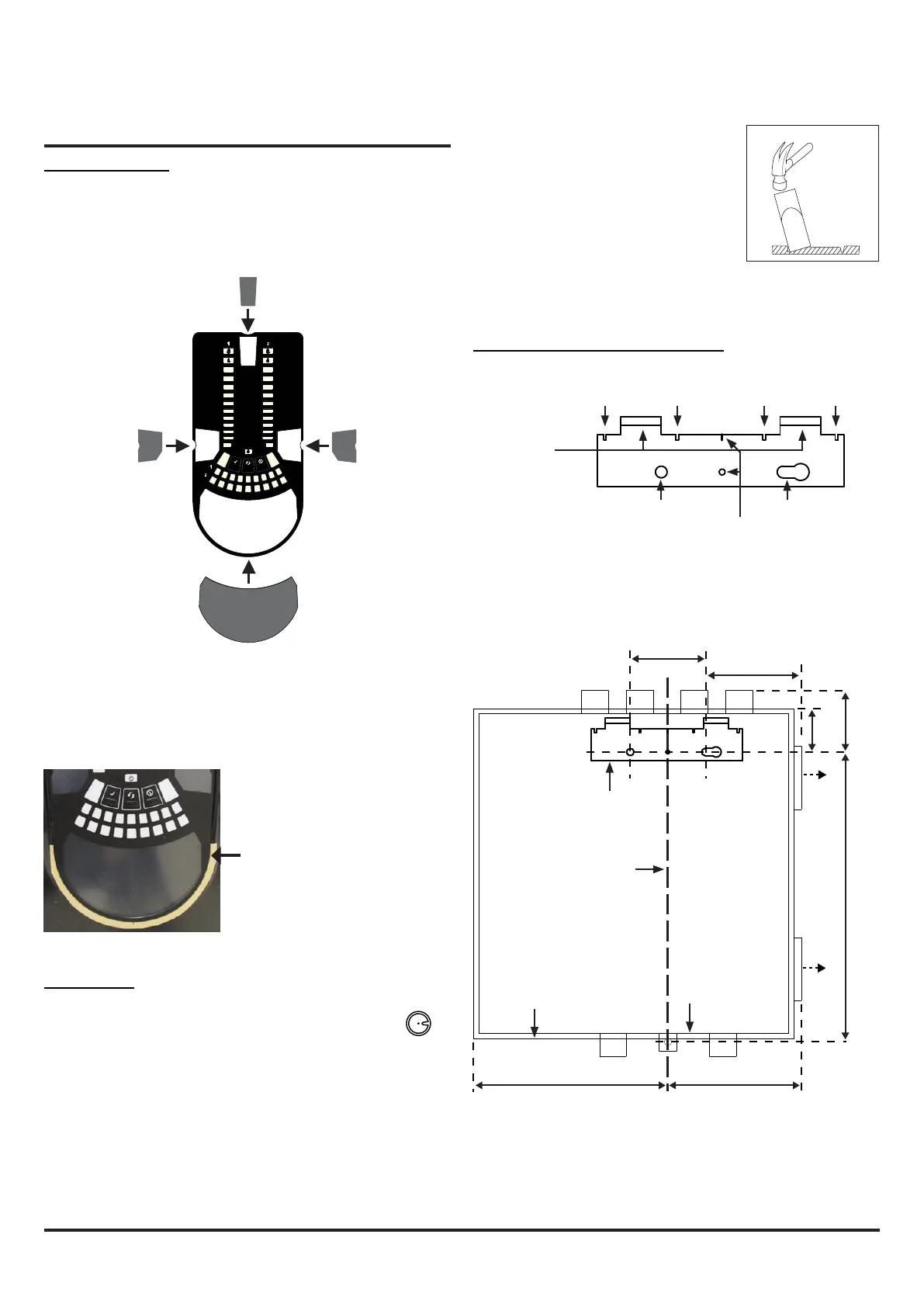
Figure 4: How to Knock Out Cable
Gland Holes
Figure 3: Remove Backing to
Stick Cover Down
When label A is in place, remove the protector from the bottom of
the clear cover to stick the cover down, as shown in Figure 3:
Cable Access
Knock out cable gland holes where required. The
location of the cable gland holes is shown in Figure 1,
represented by the icon:
This equipment and all associated pipe work must be installed in
accordance with all relevant codes and regulations.
PHYSICAL INSTALLATION
Front Panel Labels
The LT NFXI-ASD is shipped without the front panel labels xed in
place. This allows the installer to choose the language required for
the installation from the Front Panel Labelling Pack.
Figure 2 shows where the labels need to be placed:
1 2 3 4 5 6 7 8 9 10 11 12 13 14 1516 17 18
Figure 6: Fasten the mounting bracket to the wall
Mounting the LT NFXI-ASD to the Wall
Figure 2: Placing the Front Panel Labels
2
10
3
1
4
5
6
7
8
9
2
10
3
1
4
5
6
7
8
9
INPUT
SENSOR
ASPIRATOR
ELBASID/MESY
TEMPERATURE
SOUNDER
FILTER
LOW FLOW
HIGH FLOW
S
T
FAULT
POWER
LEVEL 2
SMOKE
MODULE 2
MODULE 1
LEVEL 1
SMOKE
FAULT
ALARM
PREALARM
A
Figure 5: Mounting Bracket
FAAST LT
HANGING LUGS
INDICATES CENTRE OF ASPIRATING PIPES
FIXING HOLE FIXING HOLE
USE FOR PLUMB-LINE
99 mm
59
329
212 mm
144 mm
41
mm
mm
mm
*
*
POSITION OF BRACKET
PLUMB LINE
BASE OUTLINE
OUTER DIMENSION OF UNIT
* Minimum clearance required from hinges to open door = 35 mm.
 Loading...


