N200-102-00 5 I56-3947-200
Table 2: Wiring Terminal Designations
(Note - Terminals marked CH2 will only be available on 2 channel
models)
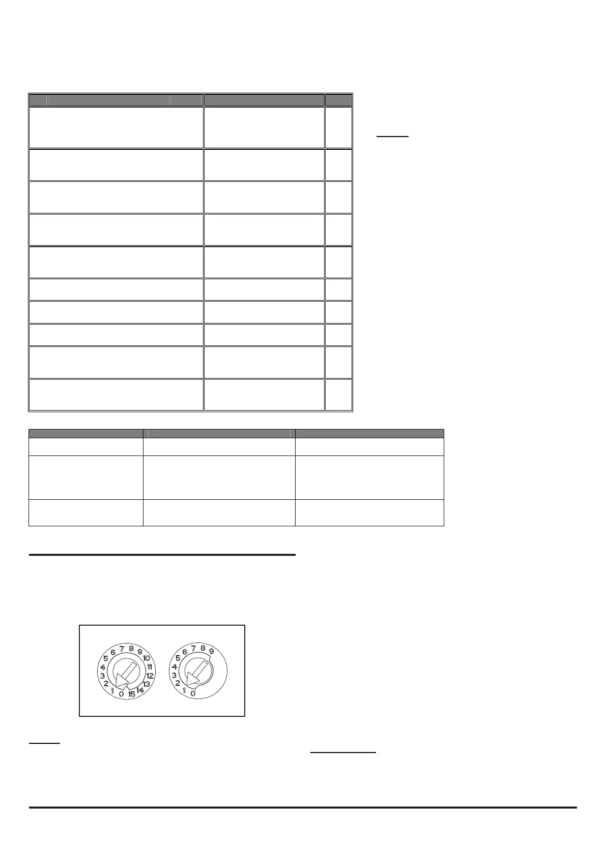
Address 1; in 2 channel units (or when two sensors
are tted) the second device is set to Address 2.
Any sensor address may be used except 0, whilst
respecting the panel’s rules on co-operative
Multi-Sensing* (see below) between the VIEW™
smoke sensors.
Module
The module address is set by means of rotary
decade address switches located behind the door
of the unit. Use a screwdriver to rotate the wheels
to the desired address. The selected address
refers to channel 1; on 2 channel units the device
assigns the next (+1) module address to channel
2 automatically. Hence, address 159 is not valid
for channel 1. (Note: for control panels that use
only 99 addresses, 99 is invalid for channel 1.)
Note: The module address will only respond to a
panel poll when in Normal mode.
* Co-Operative Multi-Sensing
Depending upon the panel used, the rules to
dene the co-operative Multi-Sensing between
the VIEW™ smoke sensors differs. This mode will
allow an even higher sensitivity, but is only to be
used for the sensors within a single NFXI-ASD12.
How to Set this up for the NF300, NF3000,
NF500 and NF5000 Panels
The co-operative Multi-Sensing is automatically
activated if the VIEW™ sensors on a loop are set
to adjacent sensor addresses and if they are also
put into the same zone. Additionally, if cells are
being used, the cell numbers for the co-operative
How to Set this up for the NF50-A, NF50, NF50-S and Pearl
Panels
The co-operative Multi-Sensing is automatically activated if the
VIEW™ sensors on a loop are put into the same cell. Setting a cell
to 0 will disable co-operative Multi-Sensing for that sensor.
IMPORTANT
If Co-operative Multi-Sensing is enabled in the panel, the two
VIEW™ sensors within an Aspirating Smoke Detector are required
to have adjacent addresses set.
If more than one Aspirating Smoke Detector is used on a loop,
ensure that the VIEW™ sensors do not have adjacent addresses
across two different Aspirating Smoke Detectors. This will cause
the panel to generate a fault message instead of a re message
when smoke is detected by one of the Aspirated Smoke Detector
units but not the other.
To avoid problems, ensure that no VIEW™ sensors on a loop have
addresses set adjacent to the address values set in an Aspirating
Smoke Detector.
POWERING UP
Using Default Settings
1. Connect a suitable 24VDC supply (complying with European
Standard EN 54-4) to pins 1 and 2 on terminal block T1 (See
Table 2)
Table 3: Relays
No. Function
1 Ext Power In +
Primary PSU
T1
2 Ext Power In -
Primary PSU
3 Aux Power In +
Not used in default
4 Aux Power In -
Not used in default
5 NC Alarm Relay
CH1
T2
6 C Alarm Relay
CH1
7 NO Alarm Relay
CH1
8 NC Alarm Relay
CH2
T3
9 C Alarm Relay
CH2
10 NO Alarm Relay
CH2
11 NC Fault Relay
CH1
T4
12 C Fault Relay
CH1
13 NO Fault Relay
CH1
14 NC Fault Relay (AUX)
CH2
T5
15 C Fault Relay (AUX)
CH2
16 NO Fault Relay (AUX)
CH2
17 Sounder Output 1 -
47 k-ohm EOL Resistor
T6
18 Sounder Output 1 +
19 Sounder Output 2 -
47 k-ohm EOL Resistor
T7
20 Sounder Output 2 +
21 Configurable Input +
(Reset)
Default is active = short circuit
(unsupervised)
T8
22 Configurable Input -
(Reset)
23 Not Used
T9
24 Loop out -
25 Loop switched out +
To use isolator
26 Loop in -
T10
27 Loop in +
28 Loop not switched out +
Internally connected to 27
RELAY ACTION: NOTES
ALARM 1 or 2 Controlled by panel when it determines
alarm condition has been met.
Set ON and OFF by panel; not latched
FAULT 1 or 2 When FAULT CONDITION on Ch1 or Ch2
or a common FAULT occurs. Fault is also
signalled when in Service Mode and when
the device is unpowered.
Fault state is not latched.
SOUNDER 1 or 2 Set ON when a channel is in ALARM.
Sounder 1 corresponds to Ch1 and
Sounder 2 corresponds to Ch2
Default condition = set on in ALARM.
SETTING THE ADDRESSES
Figure 10: Address Switches
Each aspiration channel uses loop communications to report its
status information to the CIE (Fire Panel). As a factory default,
the unit will report smoke alarm and sensor information at an
associated sensor address and general alerts and faults on a
different module address.
Sensor
The sensor address is set on rotary decade switches on the back
of the smoke sensing devices. The smoke sensors are located
under the sensor cover inside the unit (see Figure 9). The Smoke
Sensors section of Service - later in the manual - shows how
to remove the sensors. As supplied, the default for channel 1 is
sensors must also be the same.
 Loading...


