Do you have a question about the Honeywell XLS140 and is the answer not in the manual?
Lists NFPA, UL, and other standards the system complies with.
Lists related documents for system components and accessories.
Explains the meaning of CAUTION and WARNING symbols used in the manual.
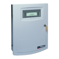
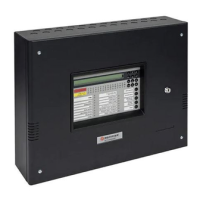
Describes the XLS140/E control panels as modular, intelligent fire alarm systems.
Lists the core features of the XLS140 control panel, including detection and notification.
Refers to system components for descriptions of optional modules.
Lists considerations for system expansion, power supply, and batteries.
Details the basic equipment required for an XLS140 system.
Lists the fundamental components needed for a basic XLS140 system.
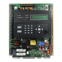
Describes the main PCB, its functions, and power supply integration.
Explains the integral power supply and battery charger functions.
Illustrates the location of connections, switches, jumpers, and LEDs on the circuit board.
Details the available CAB-4 series backbox sizes and trim rings.
Lists and describes various optional components that can be installed.
Explains how intelligent detectors provide analog information to the control panel.
Describes modules that interface between the panel and devices.
Describes modules for annunciating system status.
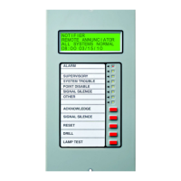
Discusses remote annunciators and their capabilities.
Details control and expander modules for 24 and 48-point annunciators.
Describes fixed modules for discrete display and control points.
Lists compatible printers and display devices for the system.
Describes modules for controlling external circuits and relays.
Explains the voice alarm system for paging and voice evacuation.
Guides on selecting a location and initial system inspection.
Lists NEC, ULC, and local codes installers must be familiar with.
A checklist for installing, wiring, and testing the XLS140 system.
Instructions for mounting the CAB-4 Series backbox to a wall.
Guidelines for deciding where to locate equipment within the backbox.
Steps for mounting the control panel CPU and display unit.
Mounting instructions for the control panel CPU and KDM-2 display.
Instructions for using the XLS-NCA as the primary display.
Steps for installing the LEM-320 to add a second SLC loop.
Instructions for installing the NCM for networking control panels.
General instructions for mounting and connecting option boards.
Procedures for connecting primary AC and secondary DC power sources.
Steps for connecting the control panel to the AC branch circuit.
Instructions for installing and connecting system batteries.
Details connections for resettable and non-resettable 24 VDC power outputs.
Explains NAC configuration and connections for releasing circuits.
Describes connections for Alarm, Trouble, Supervisory, and Security relays.
Explains the function of backup alarm switches for NAC activation.
Refers to TM-4 installation document for details.
Outlines requirements for separating power-limited and non-power-limited wiring.
Overview of installing expander boards and modules.
Steps for mounting expander boards onto their respective modules.
Shows wiring setup for connecting panel circuit modules to the control panel.
Steps for installing panel circuit modules into the chassis.
Details current limitations for ICM-4RK/ICE-4 NAC connections.
Provides guidelines for field-wiring ICM-4RK and ICE-4 modules.
Details the product-specific information for the ARM-4 module.
Instructions for installing the Auxiliary Relay Module in the chassis.
Explains field wiring and contact ratings for the ARM-4 module.
Instructions for connecting and configuring printers and CRT terminals.
Details connecting and setting options for the PRN series printer.
Instructions for connecting and setting up a Keltron printer.
Details connecting and setting parameters for a CRT-2 terminal.
Instructions for connecting a PC for programming via EIA-232.
Explains SLC wiring requirements and capacity for intelligent devices.
Introduces application chapters covering NFPA standards and system uses.
Explains UDACT wiring for central/remote station fire alarm systems.
Describes UDACT connection for proprietary fire alarm systems.
Guides on using the panel as a combined Fire/Security system.
Explains how the panel functions as a combination Fire/Security system.
Instructions for wiring the cabinet with a security tamper switch.
How to program security devices and select Type Code SECURITY.
Shows typical wiring for proprietary security alarm applications.
Details agent release and preaction/deluge control applications.
Lists NFPA standards for agent release applications.
How to map zones to activate releasing outputs.
References wiring diagrams for releasing applications.
Details connecting a releasing device to the control panel NACs.
How to connect a releasing device to the CM-N/TC810N1013 module.
Typical connections for the NBG-12LRA station.
Procedures for conducting a complete operational test after installation.
Schedules and procedures for regular system testing and maintenance.
Monthly checks to ensure proper system operation between formal tests.
Guidelines for maintaining and replacing system batteries.
How to determine the total AC current required for the system.
How to calculate system current draws for standby and alarm conditions.
Determines maximum current needs for secondary power during fire alarms.
Table and guidance for determining the necessary battery capacity.
Table to determine the battery capacity needed for the system.
Table to choose battery size based on calculated amp-hours.
Lists AC power and battery charger specifications.
Details wire types and gauges for different system circuits.
Lists common Honeywell and Notifier devices compatible with the system.
Lists common System Sensor devices compatible with the system.
Describes standalone application configurations for Canada.
Details using KDM-2 as primary display in Canada.
Details using XLS-NCA as primary display in Canada.
ULC requirements for network operation in Canada.
Consult AHJ for this feature in Canadian annunciator systems.
Specifies ACM series modules and LED colors for Canadian applications.
Supervision requirements for releasing devices in Canada.
| Type | Addressable Fire Alarm Control Panel |
|---|---|
| SLC Loops | 1 |
| NAC Outputs | 4 |
| Communication Ports | RS-232, RS-485 |
| Operating Temperature | 32°F to 120°F (0°C to 49°C) |
| Humidity Range | 10% to 93% non-condensing |
| Certifications | UL, FM, CSFM |
| Networking | Optional |
| Releasing Capability | Yes |


