56 XLS140 Installation Manual Form Number 95-7673-3 P/N 51927:C 12/06/2005
Installation Wiring a Signaling Line Circuit (SLC)
3.15 Wiring a Signaling Line Circuit (SLC)
Overview
Communication between the control panel and intelligent and addressable initiating, monitor, and
control devices takes place through a Signaling Line Circuit (SLC). You can wire an SLC to meet
the requirements of NFPA Style 4, Style 6, or Style 7 circuits. This manual provides requirements
and performance details specific to this control panel; for installation information and general
information, refer to the SLC Wiring Manual.
Wiring
Maximum wiring distance of an SLC using 12 AWG (3.31 mm
2
) wire is 12,500 feet (3810 meters)
total twisted-pair for Style 4, Style 6 and Style 7 circuits.
Capacity
The XLS140 provides one (1) SLC, with a total capacity of 318 intelligent/addressable devices:
• 01-159 intelligent detectors
• 01-159 monitor and control modules
An optional expander board provides one (1) additional SLC, with the same capacity.
Installation
This control panel supports one or two SLC loops; a second SLC loop is obtained by installing an
LEM-320 module. SLC loop #1 connects to TB16 on the control panel; SLC loop #2 connects to
TB1 on the LEM-320. For details on designing, installing and configuring SLC loops, see the SLC
Wiring Manual.
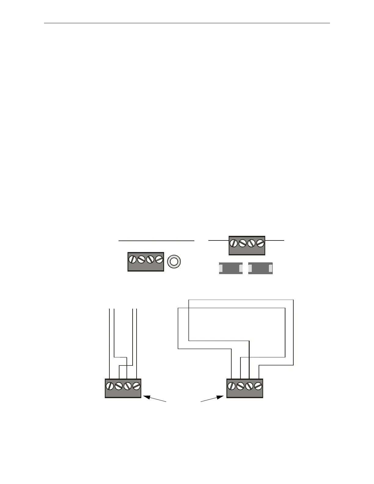
B+ A+ B- A- B+ A+ B- A-
T-Tapping is not allowed
on a four-wire SLC.
SLC B (output loop)
SLC A (loop return)
SLC B SLC A
Style 4 SLC Loops Style 6 SLC Loops
TB1
B+ A+ B- A-
SLC1
B+ A+ B- A-
TB16
SLC Loop #2 Connections
on Loop Expander Module
SLC Loop #1 Connections
on FACP’s main circuit board
Use either
SLC Loop #1
or SLC Loop #2
nfs640-slcloops.cdr, nfs640-slc-tb.cdr, LEM320-slc-tb.cdr
Figure 3.30 SLC Loop Connections and Wiring

 Loading...


