36 XLS140 Installation Manual Form Number 95-7673-3 P/N 51927:C 12/06/2005
Installation Installing the Control Panel
3.5.3 Loop Expander Module
Installing a Loop Expander Module adds a
second SLC loop to the control panel. Refer
to the Figure 3.6 for connector illustrations.
1. Thread four (4) 0.937 inch (23.8 mm)
stand-offs through indicated holes in the
XLS140-CPU board.
2. Plug stacker-connector into J3 on the
XLS140-CPU.
3. Lay the LEM onto the standoffs and
connect the Loop Expander Module
(LEM) into the stacker-connector
attached to J3.
4. Attach LEM using screws provided with
the module.
5. After LEM is mounted on the control
panel, connect the SLC loops to TB1 on
the LEM and TB16 on the
XLS140-CPU. This system supports
either FlashScan or CLIP mode devices.
Refer to the SLC loop manual for wiring requirements and specific details.
J1
B+
+B-
-
LEM-320PCA
TB1
B+ A+ B- A-
TB1
Lem-slc.cdr
Figure 3.5 SLC Connections for LEM-320
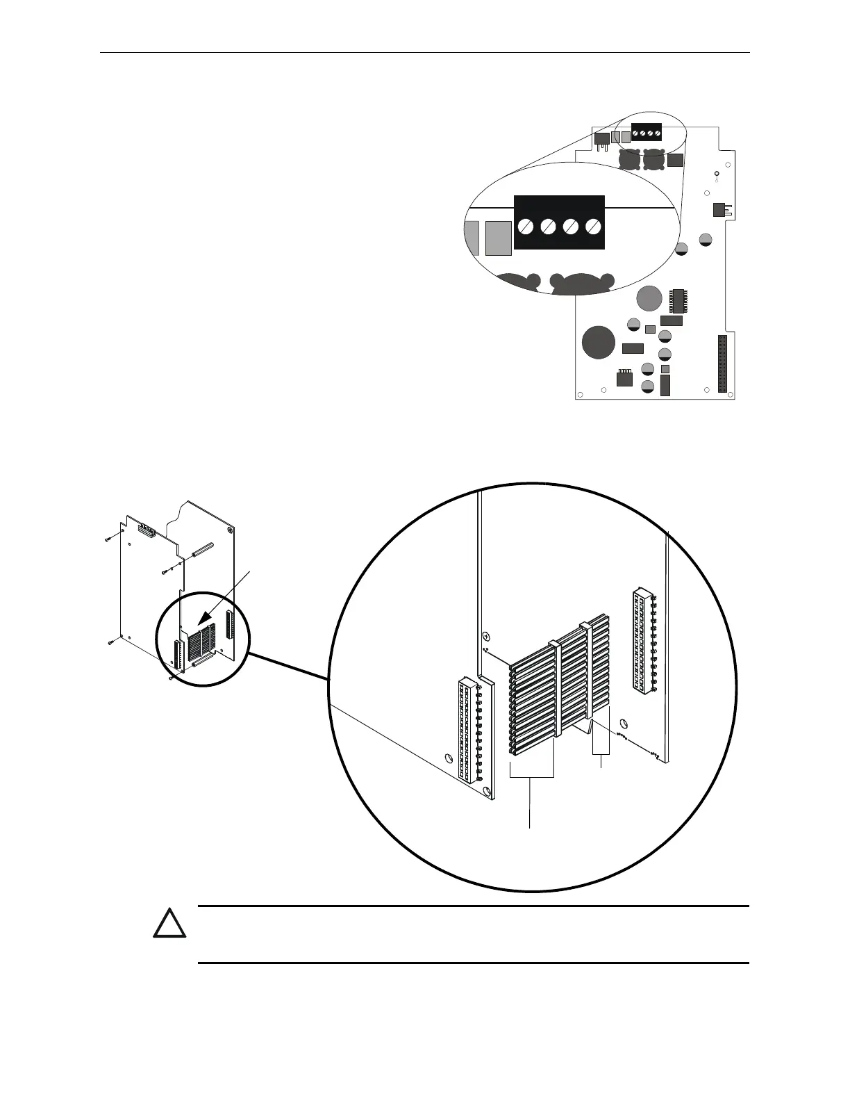
XLS140-CPU
Stacker-connector
LEM-320
J1
J3
The long-pin end
plugs into the back
of the LEM board.
The short-pin end plugs
directly into the top of the
XLS140-CPU plug.
!
CAUTION:
If the stacker-connector is installed incorrectly, the short-pin end of the plug can fail to make a secure
connection when plugged through the back of the LEM.
Figure 3.6 Mounting LEM-320 with the Stacker-connector

 Loading...


