60 XLS140 Installation Manual Form Number 95-7673-3 P/N 51927:C 12/06/2005
Applications NFPA 72-1999 Central or Remote Station Fire Alarm System (Protected Premises Unit)
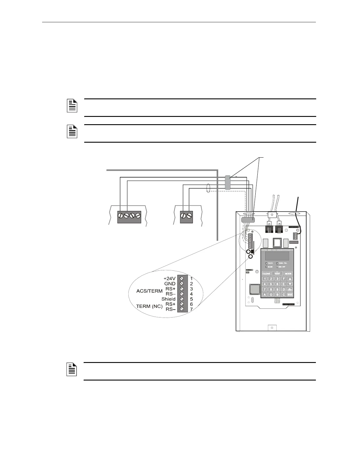
4.2 NFPA 72-1999 Central or Remote Station Fire Alarm
System (Protected Premises Unit)
Figure 4.1 shows typical wiring diagram for a NFPA 72-1999 Central Station Fire Alarm System
(Protected Premises Unit) or a Remote Station Fire Alarm System (Protected Premises Unit) using
the Universal Digital Alarm Communicator/Transmitter (UDACT) and control panel. This
provides typical wiring only; connect and program the UDACT according to the directions given in
the UDACT Instruction Manual.
NOTE: An NFPA 72-1999 Central Station requires 24 hours of standby power; an
NFPA 72-1999 Remote Station requires 60 hours of standby power.
NOTE: This application can also be done with the TM-4 Transmitter; refer to the Transmitter
Module TM-4 document for more details.
TB13
EIA-485
+ ACS –
24V NONRST 24V RESET
+ – +
–
TB7
UDACT in ABS-8R
(shown with cover removed)
Solid earth
ground
To supervised
phone lines
Ferrite cores
P/N 29090
FACP Cabinet
EIA-485
(ACS Mode)
24 VDC
Nonresettable power
Supervised and power-limited
EIA-485 and power wiring
nfs640-udact.cdr
Figure 4.1 Typical Wiring Diagram for a Central Station Fire Alarm System
NOTE: Install a UL-listed 120 ohm End-of-Line resistor (P/N 71244) UDACT TB1 terminals 3
and 4 if this is the last or only device on EIA-485 line.

 Loading...


