XLS140 Installation Manual Form Number 95-7673-3 P/N 51927:C 12/06/2005 45
Installing Panel Circuit Modules Installation
Refer to Section 2.10 “Panel Circuit Modules” for a complete list of modules and their expanders.
3.12.2 Mounting Expander Boards
Expander Board Modules, such as ICE-4 or CRE-4, need to be mounted onto their respective
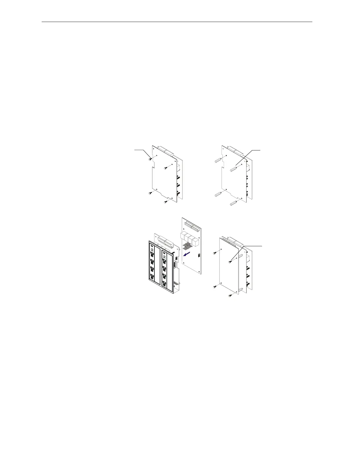
modules (ICM-4RK, CRM-4RK) prior to installation onto a chassis. Figure 3.17 illustrates the
steps to mount an Expander Module:
1. Remove one module support screw and set it aside for later use.
2. Replace the module support screw with one module stand-off.
3. Repeat Steps 1 and 2 for the three remaining module support screws.
4. Insert pins on the front of the expander board into connector on the back of the module. Make
sure the pins are in line; then, press the two units together until they snap into place.
5. Install the four module support screws (removed earlier) through the back of the expander
board and into the stand-offs. Tighten securely.
3.12.3 Connecting Ribbon Cables for a CAB-4 Series Backbox
Expander Row Ribbon Cables connect panel circuit modules to the Control Panel.
Figure 3.18 shows a typical wiring setup using two Expander Row Ribbon Cables (P/N 71088) to
connect the control panel to two rows of four (4) panel circuit modules each below the Control
Panel in a CAB-4 Series backbox.
Install module
stand-off
Remove existing
module support
screw
Plug in the expander board
Secure with module
support screws
nfs640-pcmods.cdr
Steps 1 & 2
Steps 4 & 5
Figure 3.17 Expander Module Installation

 Loading...


