50 XLS140 Installation Manual Form Number 95-7673-3 P/N 51927:C 12/06/2005
Installation Auxiliary Relay Module (ARM-4): Product-Specific Details
• Install two (2) mounting stand-offs onto the studs of the chassis, at the selected location, as
shown in Figure 3.8 on page 38 and Figure 3.25. Tighten securely.
• Install three (3) support stand-offs, with screws, onto the PC board in the locations shown in
Figure 3.8 or in the two right-hand positions on the first row. Tighten securely.
• Position module over the stand-offs on the chassis; fasten the module to the chassis with the
two (2) retaining screws. Tighten securely.
• Connect one end of the Cable (P/N 71092) to plug P1 on the ARM-4.
Note: The other end of the cable is connected to jumper JP5 on the CRM-4RK or CRE-4.
• Connect all available external wiring at this time. Refer to Section 3.13.3 “Field Wiring an
Auxiliary Relay Module”.
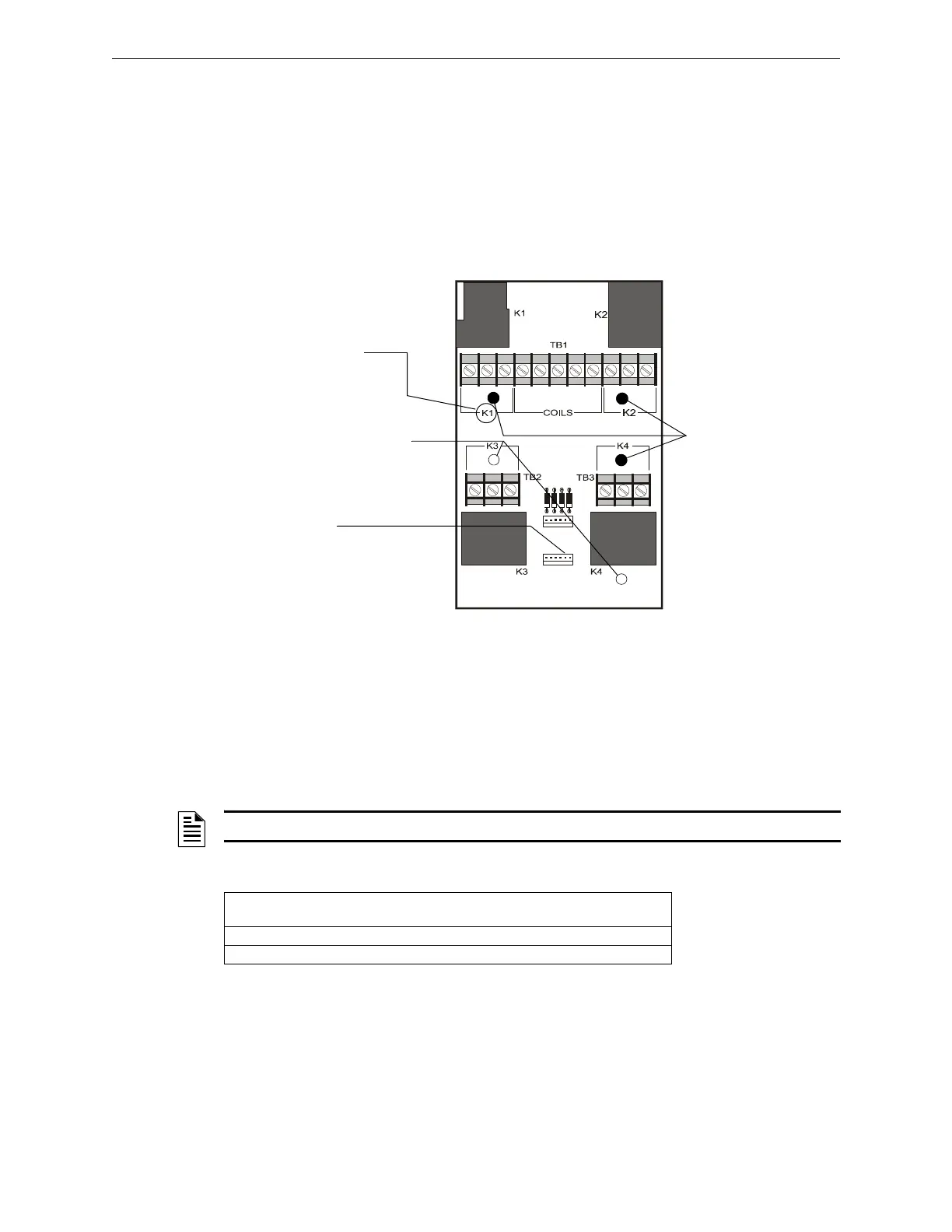
3.13.3 Field Wiring an Auxiliary Relay Module
The figure above shows terminal assignments for ARM-4 module control relays K1-K4, which
control nonpower-limited circuits. Power-limited and nonpower-limited circuit wiring must remain
separated by at least 0.25 inch (6.35 mm) within the cabinet and exit the cabinet through different
knockouts, conduits, or both.
The table contains contact ratings for relays K1-K4 on the ARM-4 module:
P2
P1
NC NO C
NC NO C
NC NO C
NC NO CCom K1 K2 K3 K4
– + + + +
ARM-4.cdr
P-1
Connection for
Cable P/N 71092
These 3 holes for
support stand-offs.
(Also see Figure 3.8
on page 38 for
chassis drawing.)
These 2 holes for
mounting stand-offs.
Terminal
Assignments
(typ. 4 places)
Figure 3.25 ARM-4 Stand-off and Terminal Locations
NOTE: For more information, refer to Section 3.11 “UL Power-limited Wiring Requirements”.
Resistive Load
Contacts
Normally Open (N.O.) Normally Closed (N.C.)
125 VAC 20 A 10 A
30 VDC 20 A 10 A
Table 3.4 Contact Ratings for K1-K4 on the ARM-4 Module

 Loading...


