XLS140 Installation Manual Form Number 95-7673-3 P/N 51927:C 12/06/2005 63
Fire/Security Applications Applications
4.4.4 Programming
The control panel can communicate with any number of security devices. To do so, program the
points as follows:
1. Select the address of the module(s) to be used for security.
2. Select the Type Code
SECURITY.
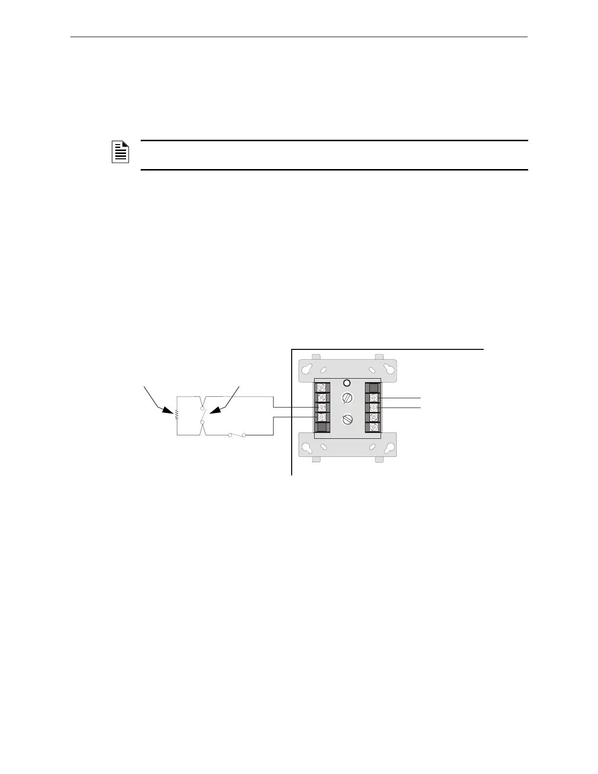
4.4.5 Wiring for Proprietary Security Alarm Applications
Table 4.4 shows typical wiring for proprietary security alarm applications with XLS-MM-A/
TC809A1059 modules. Note the following:
• The module is programmed with software
SECURITY Type Code.
• Supplementary use only applies to UL-listed systems.
• NAC devices used for security cannot be shared with fire NAC devices.
• Refer to the Device Compatibility Document for compatible NAC devices.
• All monitor modules used for security application must be installed in the XLS140 cabinet
with STS-1 Security Tamper Switch.
Figure 4.4 Wiring Diagram for Proprietary Security Alarm Applications
NOTE: For detailed instruction on programming Type Codes, refer to the XLS140 Programming
Manual.
8
9
8
8
9
9
10
11
12
13
14
150
0
1
1
2
2
3
3
4
4
5
5
6
6
7
7
0
1
2
3
4
7
6
5
TENS
ONES
DDRESS
LOOP
+
XLS-MM-A
(Note: TC809A1059 has same connections)
UL-listed, normally-closed
security switch
UL-listed,
normally-open
security switch
SLC
Channel
A or B
XLS140 Protected Premises Unit
nfs640-burg.cdr
UL-listed 47K
End-of-Line Resistor
(provided with module)

 Loading...


