XLS140 Installation Manual Form Number 95-7673-3 P/N 51927:C 12/06/2005 47
Installing Panel Circuit Modules Installation
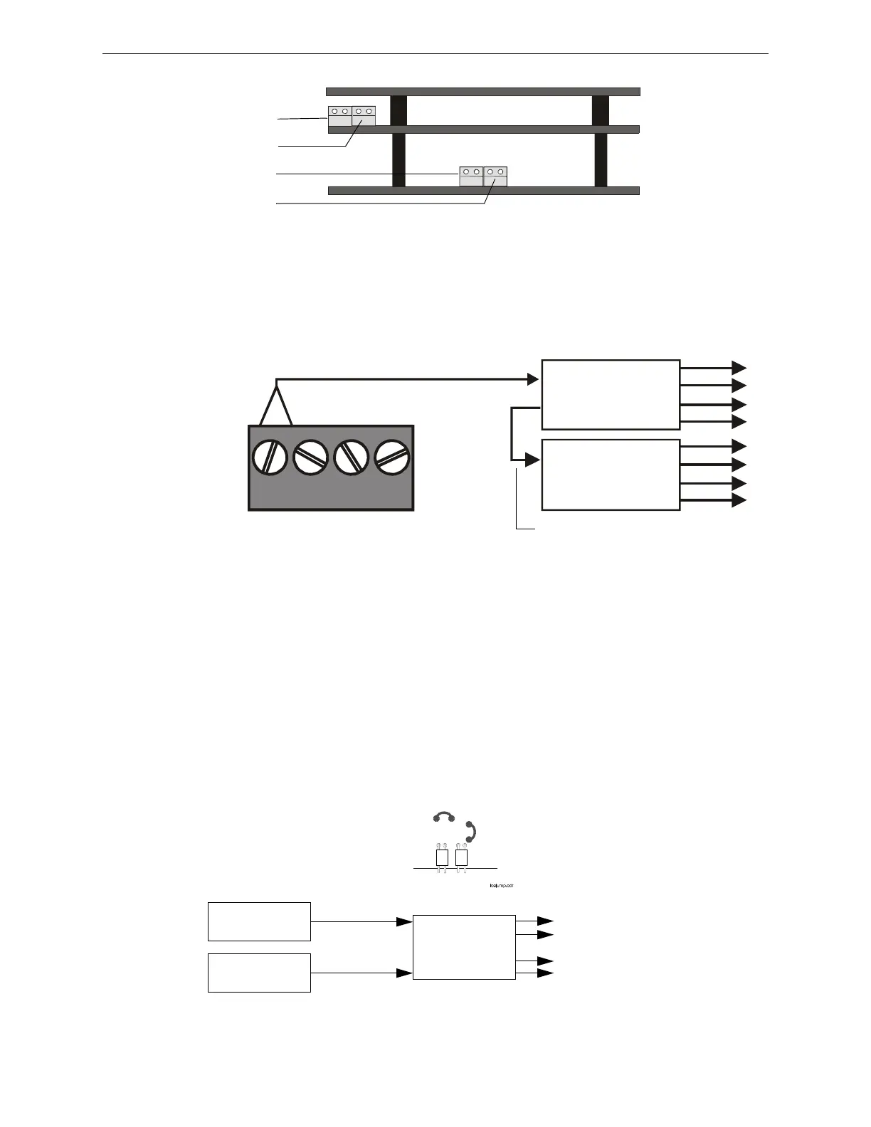
Power Supply Connections
Figure 3.20 illustrates typical connections from main power supply.
Multiple Power Supplies
Cut JP1 and JP2 on ICM-4RK when supplying 24V power from two separate sources to the
ICM-4RK. ICM-4RK circuits 1-2 will receive their power from J5; ICM-4RK circuits 3-4 will
receive their power from J6.
Cut JP1 and JP2 on ICE-4 when supplying power from separate sources to expander circuits 5-8.
ICM-4RK circuits 5-6 will receive power from J5 on the ICE-4 and ICM-4RK circuits 7-8 will
receive power from J6 on the ICE-4.
See Figure 3.21 for jumper locations.
nfs640-icmconn.cdr
ICM-4RK
ICE-4
J5
J6
J5
J6
Figure 3.19 ICM-4RK/ICE-4 Connectors
J5
ICM-4
J6
ICE-4
J5
TB7
24V 24V RESETNONRST
+ – + –
Power Cable P/N 71091
nfs640-icmnac.cdr
Eight NACs that
share 1.25 A
TB7 on Control Panel
Bell power cable (P/N 75400) or
alternate Power Harness (P/N 71093, with
lugs removed and wires stripped)
Black wire (–), Blue wire (+)
Figure 3.20 Main Power Supply Connection
ICM-4RK/ICE-4 Jumpers
APS-6R #1
APS-6R #2
J6
J5
JP1
JP2
ICM-4RK
J6
J5
Two circuits that
share 3 A of one
APS-6R (#1)
Two circuits that
share 3 A of one
APS-6R (#2)
Figure 3.21 Sample ICM-4RK Configuration for Multiple Power Supplies

 Loading...


