62 XLS140 Installation Manual Form Number 95-7673-3 P/N 51927:C 12/06/2005
Applications Fire/Security Applications
For bypass of security zones, use the DISABLE routine (covered in the Status Change section of
the XLS140 Operations Manual) for Security type devices.
4.4.2 Installing a Security Tamper Switch
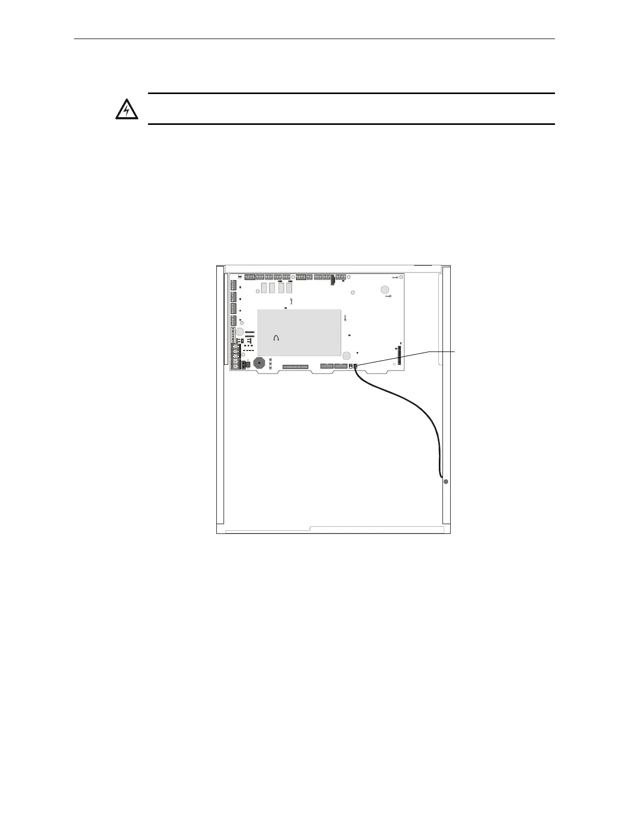
To wire the cabinet with a Security Tamper Switch kit model STS-1, refer to Figure 4.3:
1. Install the STS-1 Tamper Switch onto the side of the backbox opposite the door hinge, pushing
the switch through the opening until it snaps into place.
2. Install the magnet on the same side of the cabinet door as the lock. Push the magnet through
the opening in the door until it snaps into place.
3. Connect the STS-1 connector to J10 (Tamper) on the Control Panel.
4.4.3 Receiving Unit
For applications requiring transmission of security alarm information to a central receiving unit, the
control panel may be connected via a UDACT to a compatible receiving unit (see the UDACT
Manual). For information on configuring the Receiving unit for Combination Fire/Security
applications, refer to the documentation for that control panel.
!
WARNING:
Damage can result from incorrect wiring connections.
nfs640-sts1.cdr
STS-1 mounting location
(side opposite of door hinges)
Connect to
J10 “Tamper”
Figure 4.3 Installing the STS-1 Security Tamper Switch

 Loading...


