XLS140 Installation Manual Form Number 95-7673-3 P/N 51927:C 12/06/2005 31
Laying Out Equipment in Cabinet and Chassis Installation
• Mount the backbox on a surface that is in a clean, dry, vibration-free area.
Follow the instructions below.
1. Mark and pre-drill holes for the top two keyhole mounting bolts (0.25 inch, 0.635 cm). Use
mounting hardware appropriate for the mounting surfaces; see UL 2017 Pull-Test
Requirements.
2. Select and punch open the appropriate knock-outs. (For selection guidelines, see Section 3.11
“UL Power-limited Wiring Requirements”.)
3. Using the keyholes, mount the backbox over the two screws.
4. Mark the location for the two lower holes, remove the backbox and drill the mounting holes.
5. Mount the backbox over the top two screws, then install the remaining fasteners. Tighten all
fasteners securely.
6. Feed wires through appropriate knockouts.
7. Install control panel and other components according to Section 3.5 “Installing the Control
Panel” before installing hinges and door according to CAB-3/CAB-4 Series Cabinet
Installation Document.
3.4 Laying Out Equipment in Cabinet and Chassis
The XLS140 allows for flexible system design. Follow these guidelines when deciding where to
locate equipment in the backbox.
The first row of equipment mounts in chassis CHS-M2. Mount second, third, or fourth rows of
equipment in chassis CHS-4N (panel circuit modules, see Section 3.12 “Installing Panel Circuit
Modules”), or in chassis CHS-4L (voice components, see the Voice Alarm System Manual). Some
equipment, such as the XLS-NCA and annunciators, may be door-mounted; refer to the
equipment’s documentation for instructions.
There are four basic positions available on a chassis (side-by-side); the number of modules that can
be mounted in each position depends on the chassis model and the module size.
!
CAUTION:
Unless you are familiar with the placement of components within this backbox, only use the knockout
locations provided for conduit entry.
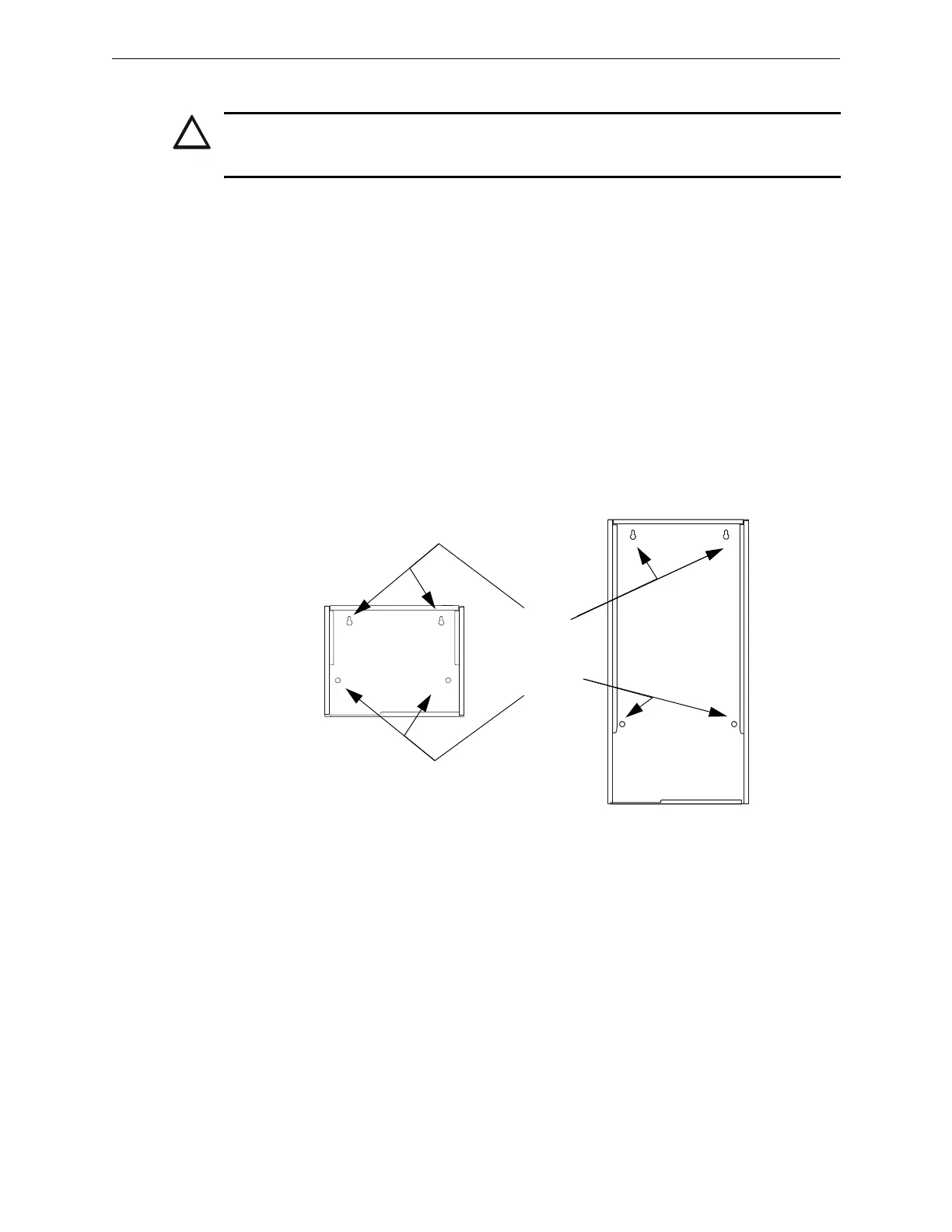
Keyholes
2 places
Mounting holes
2 places
CAB-4
Series
Backbox,
A-size
(one-row)
nfs640cabinetmountingholes.cdr
CAB-4
Series
Backbox,
D-size
(four-row)
Figure 3.1 Mounting Holes of a Backbox

 Loading...


