48 XLS140 Installation Manual Form Number 95-7673-3 P/N 51927:C 12/06/2005
Installation Installing Panel Circuit Modules
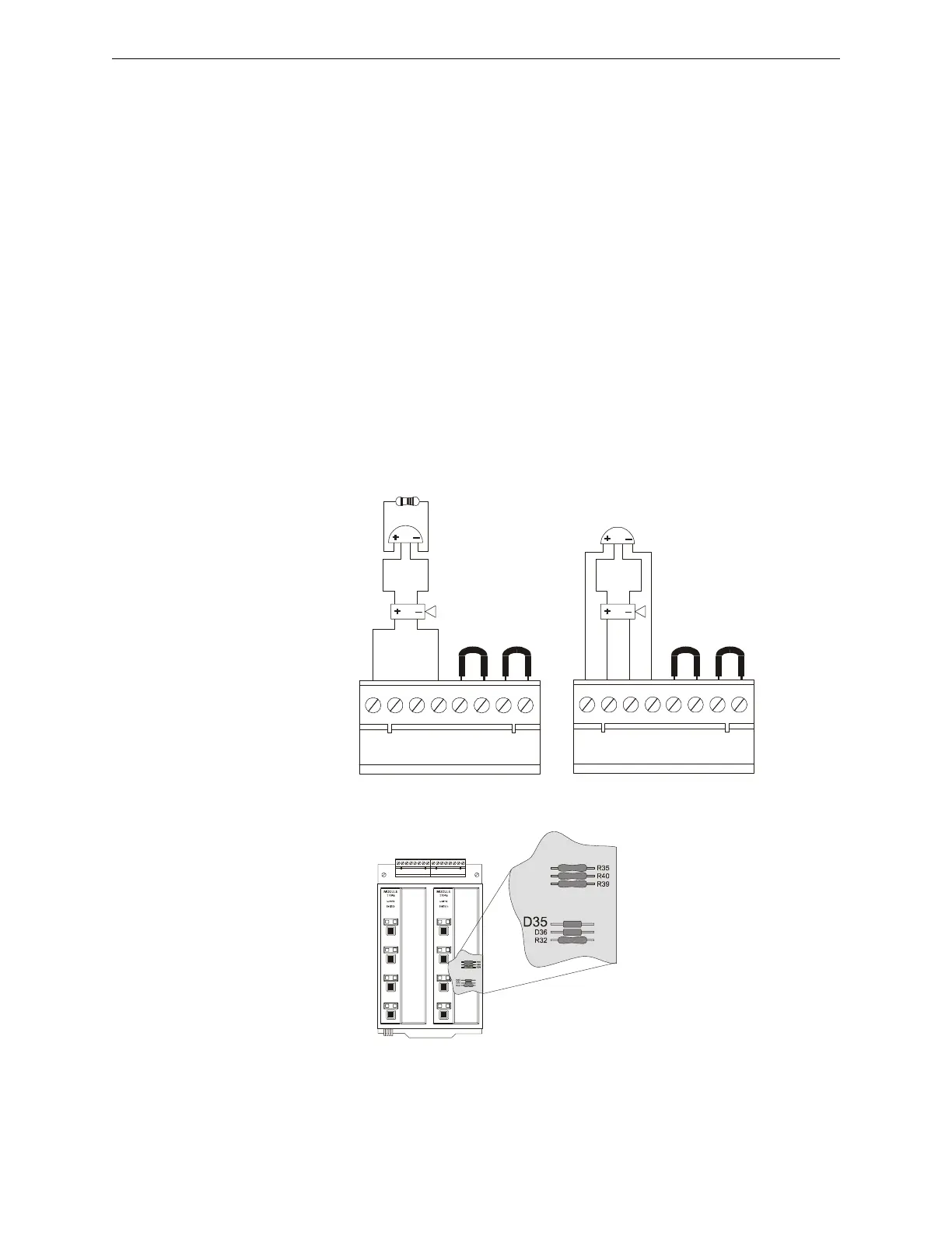
3.12.6 Field-Wiring the ICM-4RK and ICE-4 (NFPA Style Y or Z)
Guidelines for field-wiring:
• Notification Appliance Circuits (NACs) are supervised, power-limited, and can connect to a
power-limited cable.
• Use only the compatible, UL-listed notification appliances listed in the Device Compatibility
Document.
• Wire notification appliances according to the manufacturer's instructions.
• Maximum current per circuit is 3.0 A. Maximum current per module depends on the type of
power supply (standard or auxiliary).
• Canadian installations require model N-ELR End-of-Line Resistor Assembly (Style Y only).
• Size NAC wiring so the voltage drop does not exceed the minimum rated voltage of the
notification appliance used as the last device on the circuit.
• For zone coded applications, refer to the UZC-256 Universal Zone Coder manual.
• The ICM-4RK is California Code programmable (microprocessor P/N 34077 Rev. B or
higher). To program for California Code, cut diode D35 as shown in Figure 3.23. (See
appendix section of the Programming Manual for more detail.)
B+ A+ A– B– B+ A+ A– B– B+ A+ A– B– B+ A+ A– B–
Jumpers for
unused circuits
4.7K,
1/2 watt ELR
P/N 71252
UL-listed 24 VDC
Polarized Devices
ICM4wire-YB.cdr
Typical NFPA
Style Z (Class A) NAC
Typical NFPA
Style Y (Class B) NAC
Jumpers for
unused circuits
Figure 3.22 Field-Wiring an ICM-4RK/ICE-4
Cut D35 on the circuit board to
produce California code.
icm-4rk-d35.cdr
Figure 3.23 Location of D35 on ICM-4RK Circuit Board

 Loading...


