XLS140 Installation Manual Form Number 95-7673-3 P/N 51927:C 12/06/2005 15
System Components System Overview
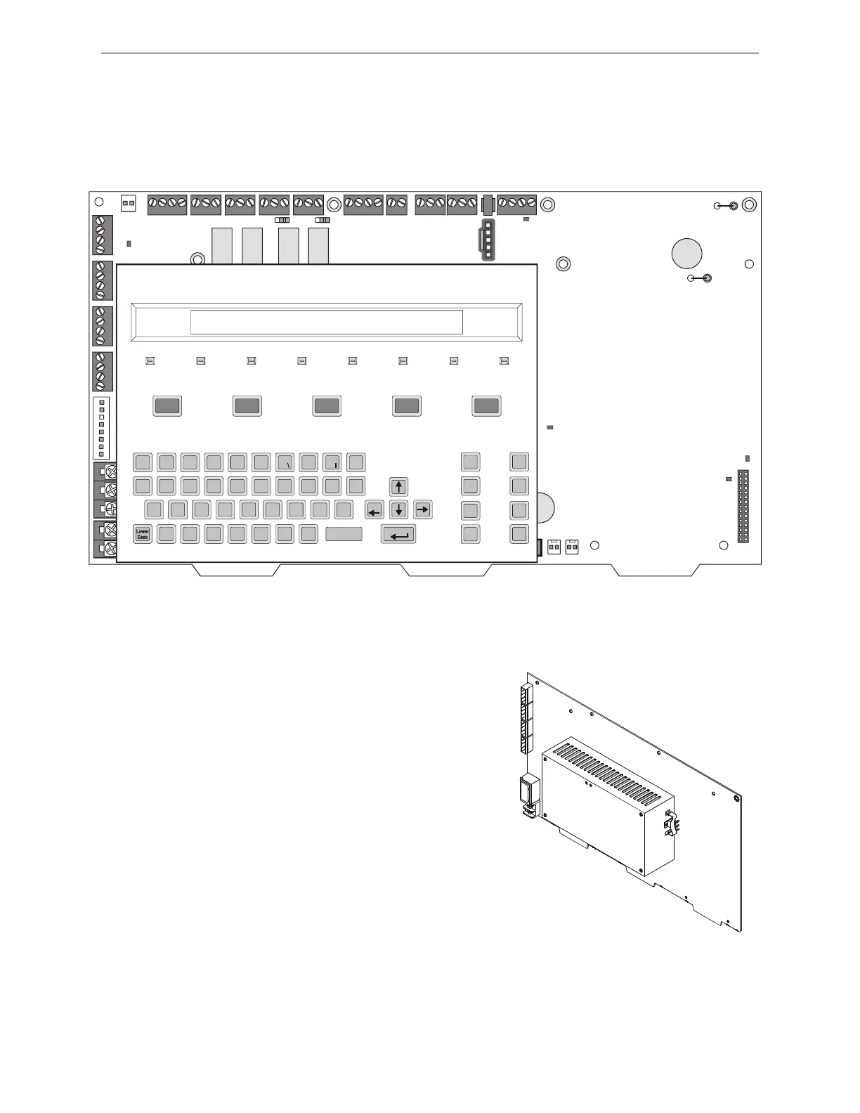
2.2.2 Control Panel Circuit Board
The control panel electronics are contained on one four-layer printed circuit board (PCB) that
incorporates a 6 amp power supply with battery charger, a signaling line circuit (SLC) and the
central processing unit. A keypad/display unit can be installed over the power supply as shown
Figure 2.1.
2.2.3 Main Power Supply
The main power supply is an integral part of the
control panel’s circuit board. It provides a total of
3 A (6 A in alarm) and contains an integral battery
charger. This can be used for many functions
including:
• Powering the XLS140
• Powering a variety of UL-listed 24 VDC
notification appliances from four built-in NAC
outputs
• Providing up to 1.25 A of resettable power for
four-wire smoke detectors
• Providing up to 1.25 A of non-resettable power
for external devices such as the TM-4
Transmitter Module.
Z X C V B N M
A S D F G H J K L
Q W E R T Y U I O P
*
#
&
/
+
–
(
)
1234567890
!
@
=
,
%: .
?
NEXT
SELECTION
PREVIOUS
SELECTION
DETECTOR
MODULE
OUTPUT
RECALL
LAST
ENTRY
INCRE MENT
NUMBER
BATTERY
LEVELS
SPACE
FIRE
ALARM
ACKNOWLEDGE
SCROLL DISPLAY
SIGNAL
SILENCE
PRE-ALARM SECURITY SUPERVISORY SYSTEM
TROUBLE
POINT
DISABLED
SIGNALS
SILENCED
POWER
DRILL
HOLD 2 SECONDS
SYSTEM
RESET
LAMP
TEST
Esc
Enter
nfs640-panel.cdr
Figure 2.1 XLS140 Control Panel with Optional Keypad/Display Unit Installed
nfs-640-panel-iso.cdr
Figure 2.2 Main Power Supply on
Control Panel

 Loading...


