16 XLS140 Installation Manual Form Number 95-7673-3 P/N 51927:C 12/06/2005
System Overview System Components
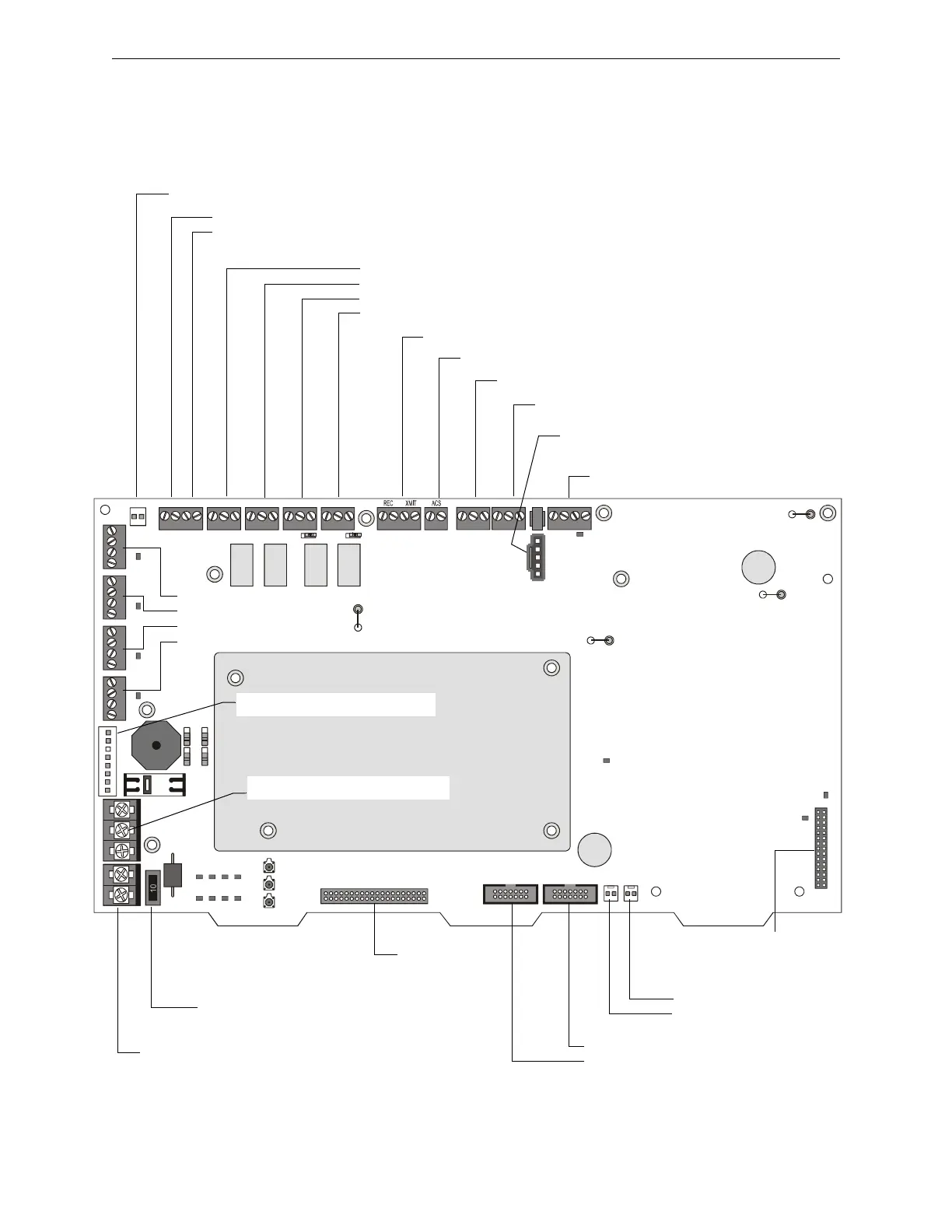
2.2.4 Circuit Board Components
The following two figures illustrate the location of the various connections, switches, jumpers and
LEDs on the circuit board. Figure 2.3 shows wiring connections. Figure 2.4 shows jumpers, LEDs
and switches. See Section 3 “Installation” for more details.
NO NO NO NONC NC NC NCCCCC
+- +- + -+ -+ -
TX RX REF TX RX REF B+ A+ B- A-
EARTH NTRL HOTBATT+BATT- B+B- A+A- B+B- A+A- B+B-A+A- B+B- A+A-
J3 - LEM-320
Connector
(SLC Loop #2)
J5 - Panel Circuits (supervised)
J10 - Security Tamper Switch
J4 - KDM-2
Connection
TB1 - Battery Connection
(over-current protected)
TB6 - NAC#1
TB5 - NAC#2
TB4 - NAC#3
TB3 - NAC#4
10 Amp Slo-Blow Fuse
P/N 12067
J7 - Accessory Power Connection
TB2 - AC Power Connection
nfs640-board2.cdr
All NAC Circuits: power-limited, supervised
TB16 - SLC #1 Connections (Detectors,
Modules) (supervised)
TB15 - EIA-232 PC/Terminal Connection (CRT)
J1 - Network/Service Connection (NUP)
(power-limited, supervised)
TB14 - EIA-232 Printer Connection
TB12 - EIA-485 Terminal Mode Connection (supervised)
TB13 - EIA-485 ACS Mode Connection (supervised)
TB7 - DC Power (24 VDC power-limited, non-resettable)
TB7 - DC Power (24 VDC power-limited, resettable)
J8 - Zone Code Input
TB8 - Alarm Relay
TB9 - Trouble Relay
TB10 - Supervisory Relay
TB11 - Security Relay
See Section 3.8 “Output Relay
Connections” for details.
J6 - Panel Circuits (supervised)
J11 - Auxiliary Trouble Input
Figure 2.3 Circuit Board Components: Wiring Connections

 Loading...


