XLS140 Installation Manual Form Number 95-7673-3 P/N 51927:C 12/06/2005 67
Releasing Applications Applications
c) Limited energy cable cannot be used to wire a non-power-limited releasing device circuit.
d) Maintain a 0.25 inch (6.35 mm) spacing between the non-power-limited releasing circuit
device wiring and any power-limited circuit wiring.
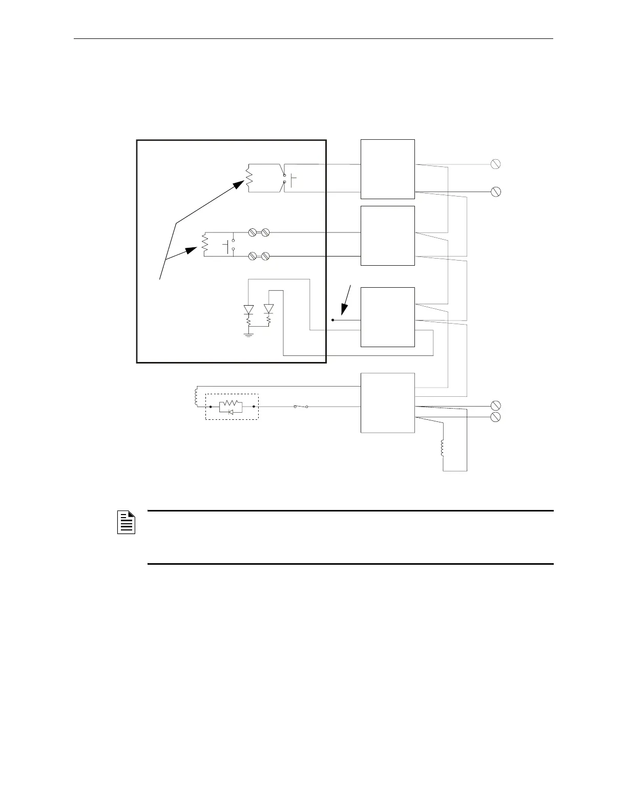
4.5.6 Connecting an NBG-12LRA Agent Release-Abort Station
NOTE: If using the on-board NACs, see Circuit Requirements for Section 4.5.4 “Connecting a
Releasing Device to the Control Panel” on page 65. If using XLS-CM-N/TC810N1013, see Circuit
Requirements for Section 4.5.5 “Connecting a Releasing Device to the XLS-CM-N/TC810N1013
Module” on page 66.
+
+
–
–
–
–
+
+
+
1
2
4
6
5
7 -
6 +
1
2
3
4
0
–
–
+
+
–
–
+
–
+
SLC loop to
FACP or LEM-320
XLS-CM-N/
TC810N1013
XLS-CM-R/
TC810R1024
XLS-MM-A/
TC809A1059
XLS-MM-B/
TC809B1008
Black
Red
Yellow
Violet
Black
Red
Yellow
Violet
Non-resettable +24 VDC
from main power supply
Manual Abort
Manual Release
Normal
Release
NBG-12LRA
See Document 51369
for installation details.
ELR mode R-47K
supervised and
power-limited
RedBrown
24 VDC UL-listed
releasing device
C.
N.O.
REL-47K
(use with Type Code
Rel Ckt ULC)
NBG640-NBG12LRA.cdr
System
Common (–)
24 VDC power
from FACP’s
main power supply
N.C.
Power Supervision
Relay (EOLR-1)
N.C. Supervision
Relay Contact
Figure 4.7 Typical Connections for an NBG-12LRA Agent Release-Abort Station

 Loading...


