44 XLS140 Installation Manual Form Number 95-7673-3 P/N 51927:C 12/06/2005
Installation Installing Panel Circuit Modules
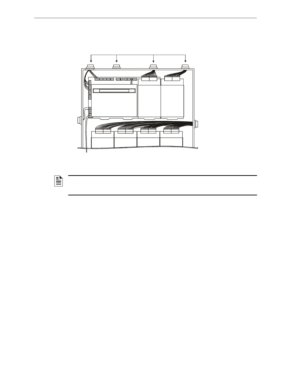
Figure 3.16 shows one configuration that meets these UL requirements. The first two rows of
modules are configured with at least a 0.25 inch (6.35 mm) separation between power-limited and
nonpower-limited wiring; AC and battery wiring is routed away from power-limited wiring.
3.11.1 Labeling Modules and Circuits
At the time of installation, each nonpower-limited circuit connected to ACM-8R, ARM-4,
CRM-4RK, CRE-4, and LDM-R32 modules must be identified in the space provided on the cabinet
door label when connected to a non-power-limited source of power.
The label lists all compatible power-limited modules and circuits; also see Figure 2.3 at the start of
this manual.
The following devices are power-limited only when connected to power-limited sources: ARM-4,
CRM-4RK, CRE-4, LDM-R32. When one of these devices is connected to a non-power-limited
source, the power-limited marking must be removed.
3.12 Installing Panel Circuit Modules
3.12.1 Overview
Installation of a panel circuit module is divided into five (5) operations:
• Mounting an optional expander board to the module (e.g. mounting ICE-4 onto an ICM-4RK).
• Connecting communication ribbon cables from Control Panel to the module.
• Installing the module onto a chassis.
• Connecting modules to the power supply.
• Field wiring the module.
Power-limited Circuits
Power-limit
ed
circuits
Nonpower-
limited
circuits
nfs640-pwrlmtwir.cdr
To cabinet-mounted battery
Figure 3.16 Typical Wiring for UL Power-limited Wiring Requirements
NOTE: AC and battery wiring are not power-limited. Maintain at least 0.25 inches (6.35 mm)
between power-limited and non power-limited circuit wiring. Install tie wraps and adhesive squares
to secure the wiring. Use a power-limited source for relay output on terminals TB8 – TB11.

 Loading...


