42 XLS140 Installation Manual Form Number 95-7673-3 P/N 51927:C 12/06/2005
Installation NAC Connections & Releasing Circuits
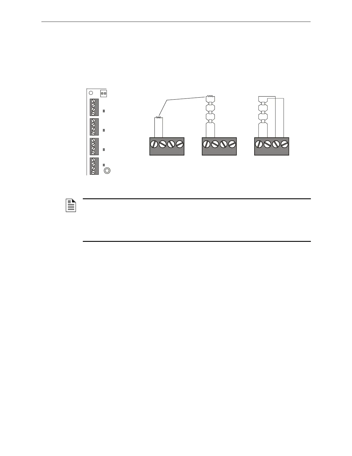
3.7 NAC Connections & Releasing Circuits
The control panel provides four NAC terminals as shown in Figure 3.12. Each can be configured as
Style Y (Class B) or Style Z (Class A) as shown in Figure 3.13. Each circuit can provide 2.5 A of
current, but the total current drawn from the main power supply cannot exceed 6.0 A in alarm
condition (refer to Table A.2). NAC circuits are supervised and power-limited. Use UL-listed
24 VDC notification appliances only (refer to the Device Compatibility Document).
3.8 Output Relay Connections
The panel provides a set of Form-C relays. These are rated for 2.0 A at 30 VDC (resistive):
• Alarm - TB8
• Trouble - TB9
• Supervisory - TB10
• Security - TB11
The Supervisory and Security contacts can also be configured as Alarm contacts by setting
switches SW1 and SW5 away from the factory default positions shown in Figure 3.14. Follow
sequence of steps in Section 3.2 “Installation Checklist”, Table 3.1; this is part of Step 6.
B+ B- A+ A- B+ B- A+ A- B+ B- A+ A- B+ B- A+ A-
Figure 3.12 NAC Terminals
TB6 - NAC#1
TB5 - NAC#2
TB4 - NAC#3
TB3 - NAC#4
nfs640-NACS.cdr
B+ B– A+ A– B+ B– A+ A– B+ B– A+ A–
nfs640-nacout.cdr
Style Y (Class B)
Connection
Style Z (Class A)
Connection
Unused Circuits
UL-listed ELR-2.2K,
1/2 W (supplied)
Figure 3.13 Notification Appliance Circuit
Connections
NOTE: Any NAC can be programmed as a releasing circuit, but only one releasing device
per circuit is allowed. For more information, refer to Section 4.5 “Releasing Applications” in this
manual and the XLS140 Programming Manual. Refer to the Device Compatibility Document for
UL-listed compatible releasing devices. Sample connections for NAC terminals are shown in
Figure 3.13. Follow sequence of steps in Section 3.2 “Installation Checklist”, Table 3.1; this is part
of Step 6.

 Loading...


