XLS140 Installation Manual Form Number 95-7673-3 P/N 51927:C 12/06/2005 73
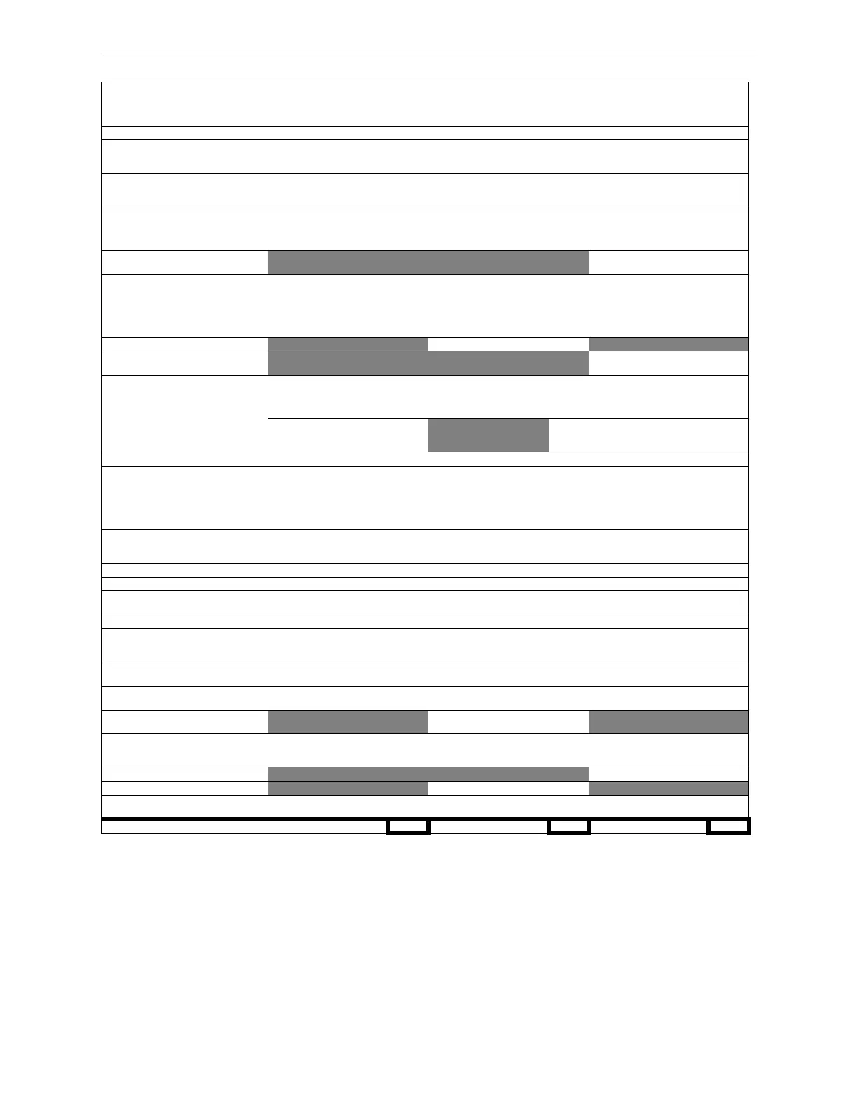
Calculating the System Current Draws Power Supply Calculations
Category
Calculation Column 1
Primary, Non-Fire Alarm
Current (amps)
Calculation Column 2
Primary, Fire Alarm
Current (amps)
Calculation Column 3
Secondary, Non-Fire Alarm
Current (amps)
Qty X [current draw]= Total Qty X [current draw]= Total Qty X [current draw]= Total
XLS140-CPU/E
KDM-2
LEM-320
1
[]
0 / 1
x [0.230] =
x [0.094]=
x [0.100]=
1
[]
0 / 1
x [0.230] =
x [0.094]=
x [0.100]=
1
[]
0 / 1
x [0.230] =
x [0.040]=
x [0.100]=
SLC loop
*
:
with jumper JP12 cut on CPU
or without jumper JP12 cut on CPU
0/1/2
x [0.200]=
x [0.400]=
0/1/2
x [0.200]=
x [0.400]=
0/1/2
x [0.200]=
x [0.400]=
XLS-NCA (back light on)
NCM-W, NCM-F
TM-4
DPI-232 (Refer to Doc. 51499)
[]
[]
[]
[]
x [0.400]=
x [0.110]=
x [0.110]=
x [ ]=
[]
[]
[]
[]
x [0.400]=
x [0.110]=
x [0.175]=
x [ ]=
[]
[]
[]
[]
x [0.400]=
x [0.110]=
x [0.110]=
x [ ]=
APS-6R
ACPS-2406
[]
[]
x [0.025]=
x [0.0013]=
ICM-4RK, ICM-4, CRM-4, CRM-4RK
ICE-4
CRE-4
DCM-4RK, DCM-4
VCE-4
VCM-4RK, VCM-4
[]
[]
[]
[]
[]
x [0.007]=
x [0.001]=
N/A
x [0.008]=
x [0.001]=
x [0.007]=
[]
[]
[]
[]
[]
x [0.072]=
x [0.065]=
x [0.065]=
x [0.080]=
x [0.040]=
x [0.040]=
[]
[]
[]
[]
[]
x [0.007]=
x [0.001]=
N/A
x [0.008]=
x [0.001]=
x [0.007]=
ARM-4 Auxiliary Relay [ ] x [0.146]=
AA-30
AA-100, AA-120
[]
[]
x [0.045]=
x [0.050]=
ACM-24AT
ACM-48A
AEM-24AT
AEM-48A
[]
[]
[]
[]
x [0.016]=
x [0.016]=
x [0.002]=
x [0.002]=
[]
[]
[]
[]
x [0.070]=
x [0.070]=
x [0.056]=
x [0.056]=
[]
[]
[]
[]
x [0.016]=
x [0.016]=
x [0.002]=
x [0.002]=
Maximum number of LEDs illuminated on
these annunciators during non-fire
conditions:
[ ] x [0.0054]= [ ] x [0.0054]=
AFM-16AT, AFM-32A [ ] x [0.040]= [ ] x [0.056]= [ ] x [0.040]=
AFM-16A
XLS-LCD-80
ACM-8R (refer to manual)
LDM (refer to Doc. 15885)
UZC-256
XLS-FDU-80
[]
[]
[]
[]
[]
[]
x [0.025]=
x [0.100]=
x [ ]=
x [ ]=
x [0.035]=
x [0.0643]=
[]
[]
[]
[]
[]
[]
x [0.065]=
x [0.100]=
x [ ]=
x [ ]=
x [0.085]=
x [0.0643]=
[]
[]
[]
[]
[]
[]
x [0.025]=
x [0.050]=
x [ ]=
x [ ]=
x [0.035]=
x [0.0643]=
AMG-1, AMG-E
FFT-7, FFT-7S
RM-1
[]
[]
[]
x [0.060]=
x [0.060]=
x [0.020]=
[]
[]
[]
x [0.060]=
x [0.120]=
x [0.020]=
[]
[]
[]
x [0.060]=
x [0.060]=
x [0.020]=
XLS-MM-Z, TC841A1000/CDN [ ] x [0.0094]= [ ] x [0.090]= [ ] x [0.0094]=
XPIQ (Refer to Doc. 51013) [ ] x [ ]= [ ] x [ ]= [ ] x [ ]=
RPT-W, RPT-WF, RPT-F
RPT-485W, RPT-485WF
[ ] x [0.017]= [ ] x [0.017]= [ ] x [0.017]=
RFX (Refer to Doc. 51012) [ ] x [ ]= [ ] x [ ]= [ ] x [ ]=
UDACT Communicator
VEC-25/50
with optional FC-AAM25
[]
[]
[]
x [0.040]=
x [0.215]=
x [0.245]=
[]
[]
[]
x [0.100]=
x [1.215]=
x [2.215]=
[]
[]
[]
x [0.040]=
x [0.215]=
x [0.245]=
Four-Wire Smoke Detectors
†
[]
[]
x [ ]=
x [ ]=
[]
[]
x [ ]=
x [ ]=
[]
[]
x [ ]=
x [ ]=
Power Supervision Relay
EOLR-1 or A77-716B
[ ] x [0.020]= [ ] x [0.020]= [ ] x [0.020]=
Notification Appliance powered from Main
Power Supply
‡
[]
[]
x [ ]=
x [ ]=
DHX-501, TC806D1018, TC806D1056/
CDN (Duct Detectors with internal relays)
Refer to installation document
[]
[]
x [ ]=
x [ ]=
[]
[]
x [ ]=
x [ ]=
[]
[]
x [ ]=
x [ ]=
CHG-120 Battery Charger [ ] x [0.060]=
Local Energy Municipal Box
[ ] x [ ]=
Compatable Devices not listed above
**
[]
[]
x [ ]=
x [ ]=
[]
[]
x [ ]=
x [ ]=
[]
[]
x [ ]=
x [ ]=
Sum each column for totals Primary, non-alarm: Primary, alarm: Secondary, non-alarm:
Table A.2 System Draw Current Calculations
* Value represents an SLC’s maximum current draw. Refer to device datasheets for individual current draws. If jumper JP12 is cut, total device current cannot
exceed 200 mA; if jumper JP12 is not cut, total device current cannot exceed 400 mA.
† The total regulated load current supplied to four-wire smoke detector and power supervision relays cannot exceed 1.25 A.
‡ Enter the total notification appliance draw from the Main Power Supply, excluding the current from APS-6R supplies. Refer to Device Compatibility Document.
** Refer to manual and/or Device Compatibility Document.

 Loading...


