XLS140 Installation Manual Form Number 95-7673-3 P/N 51927:C 12/06/2005 41
Connecting the Power Cables Installation
3. Connect the black cable from TB1(–) on the control panel to the negative (–) terminal of the
other battery.
4. Connect the remaining cable between the negative (-) terminal on the first battery to the
positive (+) terminal on the second battery.
3.6.5 APS-6R Auxiliary Power Supply Connections
If an optional APS-6R power supply is installed in the cabinet, connect it with no power applied;
follow sequence of steps in Section 3.2 “Installation Checklist”, Table 3.1; this is Step 4. For all
information pertaining to these connections see the APS-6R Instruction Manual.
3.6.6 External DC Power Output Connections
Terminal TB7 provides two (2) power outputs, resettable and non-resettable. Each output is
power-limited. Follow sequence of steps in Section 3.2 “Installation Checklist”, Table 3.1; this is
part of Step 6.
24 VDC Resettable Power Circuit (Four-Wire Smoke Detectors). The power supply
provides a single 24 VDC filtered, power-limited, resettable power circuit for devices that require
resettable power (such as four-wire smoke detectors). This circuit is power-limited, but must be
supervised. To provide supervision, install a UL-listed end-of-line power supervision relay (such as
the EOLR-1) after the last device. Connect the power supervision relay normally open contact in
series with an Initiating Device Circuit (IDC). The four-wire power circuit energizes the power
supervision relay. When you reset the system, the control panel removes power from these
terminals for approximately 15 seconds.
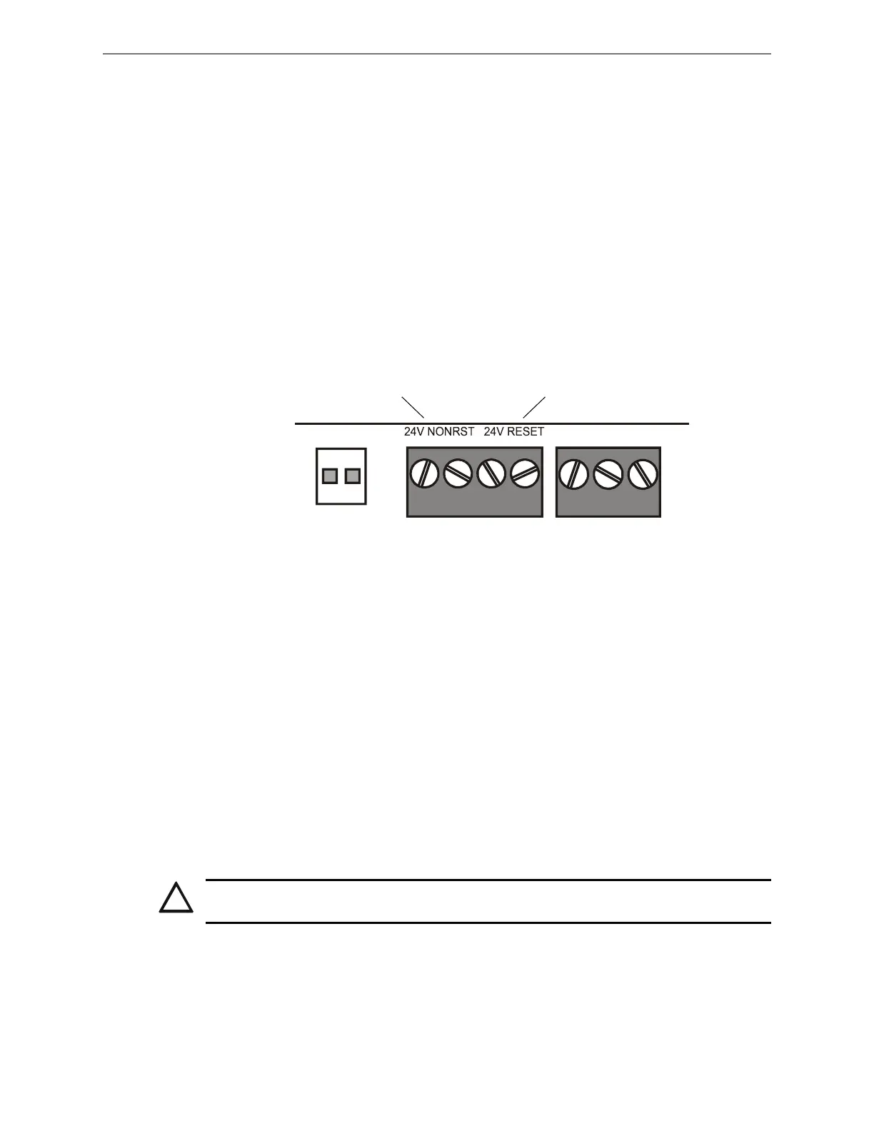
Connect external field wires to the power supply terminals TB7 RESET(+) and (–) to provide up to
1.25 A of current for powering four-wire smoke detectors. See Figure 3.11 above.
24 VDC Non-resettable Power Circuit. The power supply provides one 24 VDC filtered,
power-limited, non-resettable power output, capable of up to 1.25 A. Use this circuit to power
devices that require low-noise 24 VDC power (such as annunciators or the TM-4).
Connect external field wires to power supply terminals TB7 NONRST(+)and(–) to provide up to
1.25 A of non-resettable current for powering external devices such as annunciators. See
Figure 3.11 above.
+ – + –
TB7
Non-resettable
Power
nfs640-dcout.cdr
Resettable
Power
Figure 3.11 Power Supply DC Outputs - TB7
!
CAUTION:
During system reset, power remains at terminals TB7 NONRST(+)and(–).

 Loading...


