46 XLS140 Installation Manual Form Number 95-7673-3 P/N 51927:C 12/06/2005
Installation Installing Panel Circuit Modules
3.12.4 Installing the Panel Circuit Modules
To install a panel circuit module such as the ICM-4RK or CRM-4RK into the chassis:
1. Angle the module into the chassis so that the lower board edge slips into the chassis slots as
shown in Figure 3.7.
2. Push the upper end of the module into the upper opening in the chassis.
3. Secure the module to the chassis with the two module screws (provided with the module).
Tighten securely.
4. Connect the Ribbon Cable to the module.
3.12.5 Connecting ICM-4RK and ICE-4 Modules
The total current available for any group of Notification Appliance Circuits (NACs), other than the
four NACs on the control panel, cannot exceed the following:
• 6.0 A when powered from the APS-6R
• 1.25 A when powered from a XLS140 DC power output terminal
Figure 3.19 shows the wire connectors on the bottom of the ICM-4RK and the ICE-4 modules.
MOD UL E
TYPE
LAMP S
SWITCH
MOD UL E
TYPE
LAMP S
SWITCH
MODUL E
TYPE
LAMP S
SWITCH
MODUL E
TYPE
LAMP S
SWITCH
MODUL E
TYPE
LAMP S
SWITCH
MODUL E
TYPE
LAMP S
SWITCH
MODUL E
TYPE
LAMP S
SWITCH
MODUL E
TYPE
LAMP S
SWITCH
MODUL E
TYPE
LAMPS
SWITCH
MODUL E
TYPE
LAMPS
SWITCH
MODUL E
TYPE
LAMP S
SWITCH
MODUL E
TYPE
LAMP S
SWITCH
MODUL E
TYPE
LAMP S
SWITCH
MODUL E
TYPE
LAMP S
SWITCH
MODUL E
TYPE
LAMP S
SWITCH
MODUL E
TYPE
LAMP S
SWITCH
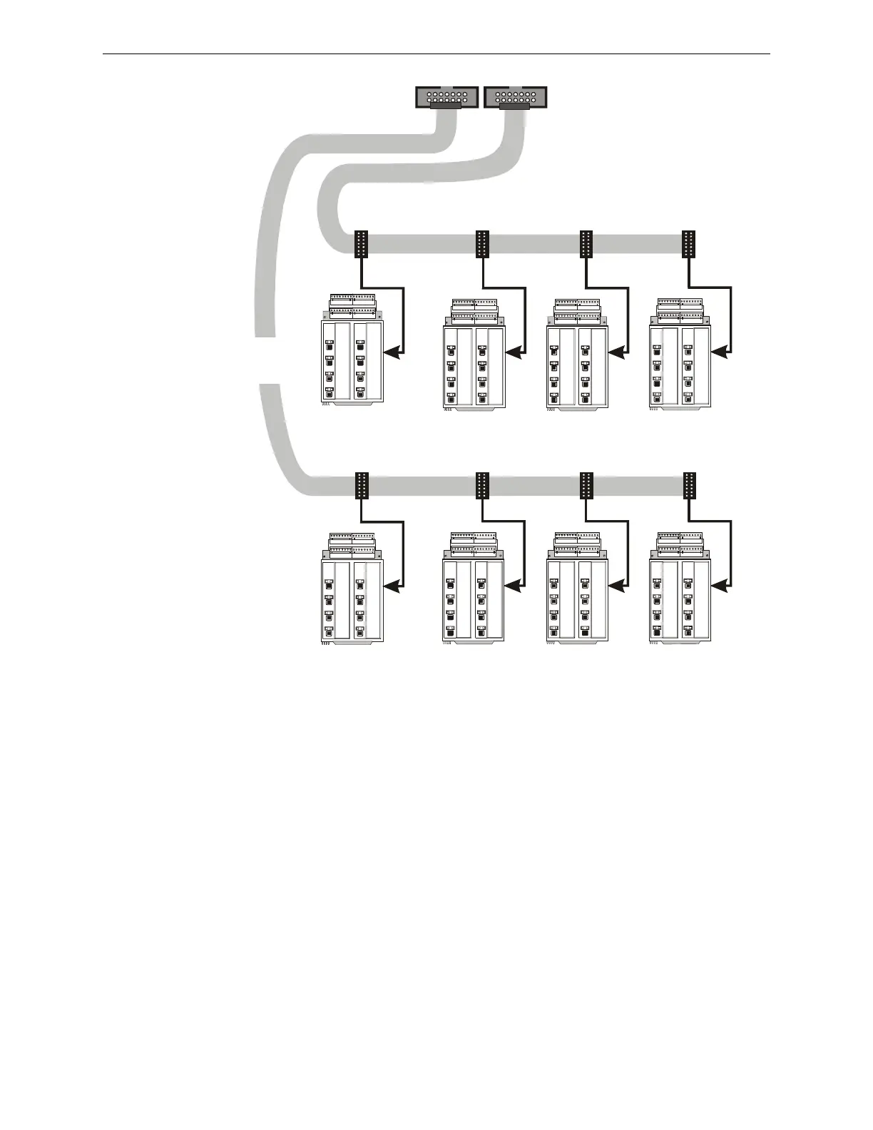
P1.1–P1.8 P2.1–P2.8 P3.1–P3.8 P4.1–P4.8
nfs640-icmribbon.cdr
Expander Row Ribbon Cable (P/N 71088)
Expander Row Ribbon Cable (P/N 71088)
Group of panel
modules in third
cabinet row
J5 - Second Row
P5.1–P5.8 P6.1–P6.8 P7.1–P7.8 P8.1–P8.8
J6 - Third Row
Group of panel
modules in second
cabinet row
Figure 3.18 Expander Row Ribbon Cable Setup

 Loading...


