40 XLS140 Installation Manual Form Number 95-7673-3 P/N 51927:C 12/06/2005
Installation Connecting the Power Cables
3.6.3 Checking AC Power
Table 3.3 contains a checklist for checking the system with AC power applied:
3.6.4 Installing and Connecting the Batteries
Batteries (2) are installed in the control panel cabinet or in a separate battery cabinet which can be
mounted below the control panel or up to 20 feet (6.096 m) away from the control panel, in conduit
in the same room.
Connect the battery as follows (see Figure 3.10 above):
1. Install batteries (2) into bottom of cabinet or into separate battery cabinet.
2. Connect the red cable from TB1(+) on the control panel to the positive (+) terminal of one
battery.
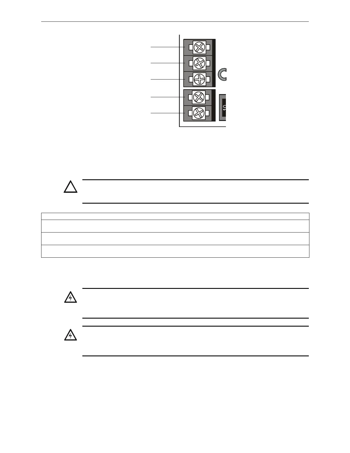
EARTH HOTNEUTRALBATT –BATT+
TB1
TB2
nfs640-acdc.cdr
Hot
Neutral
Ground
(Earth)
Battery (-)
Battery (+)
Figure 3.10 AC & DC Power Connections
!
CAUTION:
While checking AC power, make sure batteries are not connected.
Follow the sequence of steps in Section 3.2 “Installation Checklist”, Table 3.1; this is Step 16.
Component Status
Control panel circuit
board
The green AC Power indicator on; the system Trouble indicator on because batteries are not connected.
Each panel circuit
module
The yellow Trouble indicator may come on for approximately 10 seconds after applying AC power. (This
only applies to an unconfigured system.)
Each auxiliary power
supply
The yellow Trouble indicator comes on because batteries are not connected.
Table 3.3 AC Power Checklist
!
w
WARNING:
Battery contains sulfuric acid which can cause severe burns to the skin and eyes, and can destroy
fabrics. If contact is made with sulfuric acid, immediately flush skin or eyes with water for 15 minutes
and seek immediate medical attention.
!
WARNING:
Do not connect the Battery Interconnect Cables (P/N 75560 and 75561) at this time. Make this
connection AFTER initial system primary powerup. Follow sequence of steps in Section 3.2
“Installation Checklist”, Table 3.1; this is Step 17.

 Loading...


