XLS140 Installation Manual Form Number 95-7673-3 P/N 51927:C 12/06/2005 49
Auxiliary Relay Module (ARM-4): Product-Specific Details Installation
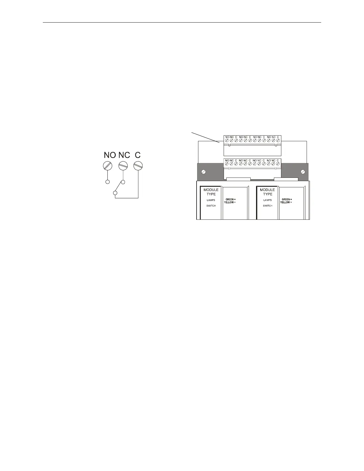
3.12.7 Connecting CRM-4RK/CRE-4 Modules
Guidelines for field-wiring the CRM-4RK and the CRE-4:
• Form-C relay contacts (silver alloy) used for medium duty switching or pilot duty.
• Terminals will accept wire sizes from 12 AWG to 18 AWG (3.31 to 0.82 mm
2
).
• Activation of a module or expander relay occurs automatically when an alarm is detected on a
programmed IDC.
• UL contact ratings are 5 A at 125 VAC (resistive) or 30 VDC (resistive) and 2 A at 125 VAC
(inductive).
• For more information, refer to Section 3.11 “UL Power-limited Wiring Requirements”.
• For typical field-wiring connections, refer to Figure 3.24.
3.13 Auxiliary Relay Module (ARM-4): Product-Specific
Details
3.13.1 Overview
If a CRM-4RK/CRE-4 is to be incorporated into the control panel and an ARM-4 is being driven by
it, note the following:
• Each ARM-4 must be supported by one CRM-4RK or one CRE-4.
• If using ARM-4’s for both modules, mount two ARM-4’s in separate positions.
• If mounted in FACP enclosure keep all non-power limited wiring separate from power limited
wiring.
For ease of installation, service, and wiring mount the ARM-4 module in a position on the chassis
that will not have any other module or expander board in front of it. However, you can install the
ARM-4 directly behind the CRM-4RK or CRE-4.
ARM-4 mounts in the second, third or fourth row of a CAB-4 series backbox, against the back of a
chassis CHS-4 or CHS-4L. The ARM-4 may be mounted in any of the 8 adjacent backbox
positions the cable can reach.
3.13.2 Installation
To install the Auxiliary Relay Module in the chassis:
• Select a mounting position for the module on the chassis.
CONTROL
RELAY
CONTROL
RELAY
Optional CRE-4 Control
Relay Expander
CREEXPCO-RK.cdr
CRM-4RK
Typical connections for a
Form-C control relay in
normal position.
Figure 3.24 Field-Wiring a CRM-4RK or CRE-4 Module

 Loading...


