XLS140 Installation Manual Form Number 95-7673-3 P/N 51927:C 12/06/2005 17
System Components System Overview
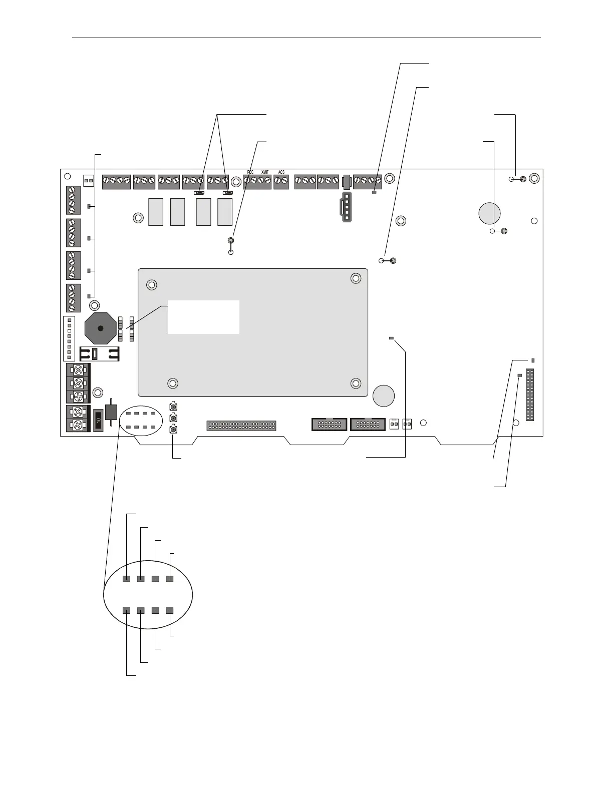
NO NO NO NONC NC NC NCCCCC
+- +- + -+ -+ -
TX RX REF TX RX REF B+ A+ B- A-
EARTH NTRL HOTBATT+BATT- B+B- A+A- B+B- A+A- B+B- A+A- B+B- A+A-
JP6 - Ground
Fault Jumper
(SLC #1)
D67 -LEM-320
Ground Fault LED
D55 - Main SLC Ground
Fault LED
JP7 - Charger
Disable Jumper
SW1, SW5 -
Relay Switches
NAC LEDs
System Switches - ‘No
Keyboard Operation’
SW2 - Acknowledge
SW3 - Silence
SW4 - Reset
Disable - Enable
Switches for
Backup Alarm
nfs640-board2.cdr
D72 - General
Board Ground
Fault LED
JP12 - 200MA
Jumper
JP13 - General Board
Ground Fault Jumper
D82 - Power-on LED
(AC or battery)
D54 - ‘AC ON’ / Power LED
D76 - Pre-Alarm LED
D77 - Security LED
D81 - Point Disabled LED
D78 - Supervisory LED
D80 - Signals Silenced LED
D79 - System Trouble LED
D75 - Fire Alarm LED
Figure 2.4 Circuit Board Components: Jumpers, LEDs and Switches

 Loading...


