N200-102-00 7 I56-3947-200
Table 4: Front Panel Indicators and Fault Descriptions
SENSO
R
A
S
P
I
R
A
T
O
R
D
R
I
F
T
C
O
M
P
E
N
S
A
T
I
O
N
TEMPERATURE / INPUT
DISABLE / SYSTEM
S
OU
N
D
E
R
F
I
L
T
E
R
LO
W
FLO
W
HI
G
H
FL
O
W
INITIALIZATION
LEVEL 1
SMOKE
FAULT
FAULT
POWER
LEVEL 2
SMOKE
INITIALIZATION
ALARM
PREALARM
2
10
3
1
4
5
6
7
8
9
2
10
3
1
4
5
6
7
8
9
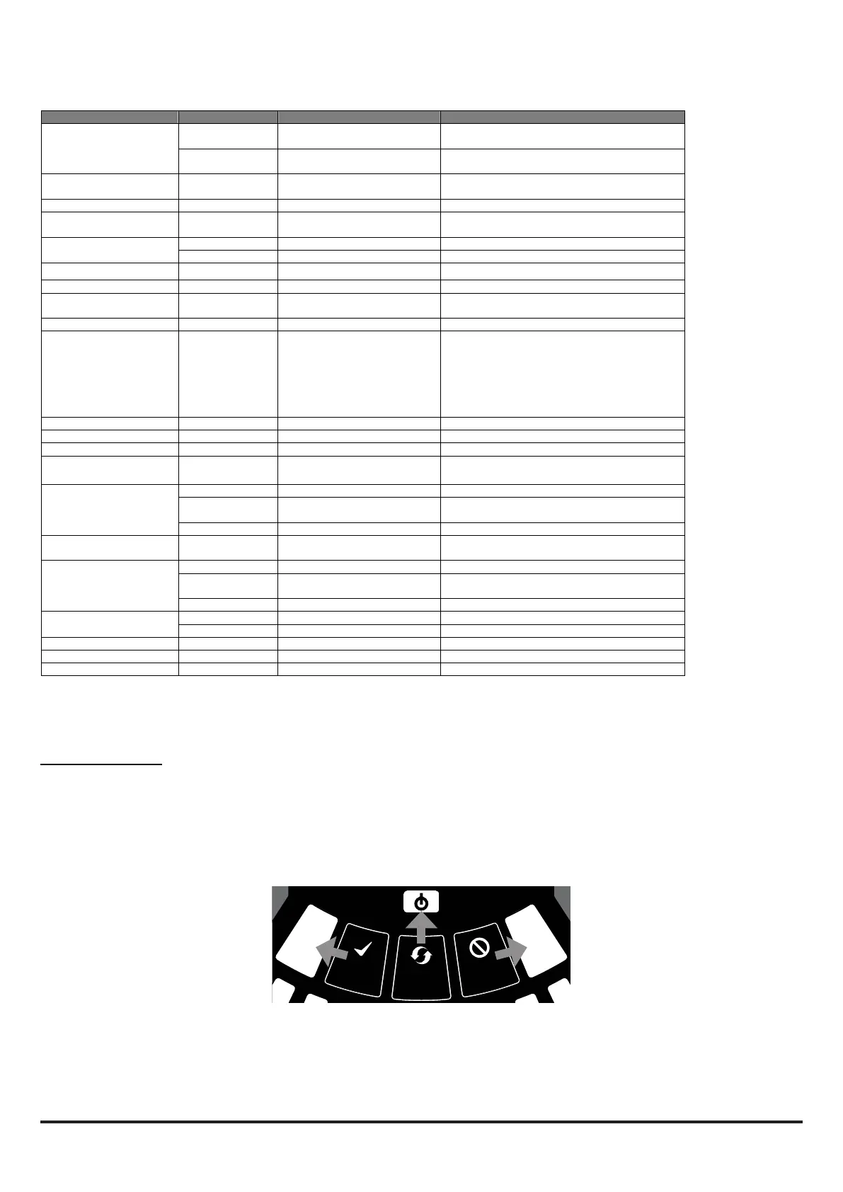
Figure 12: User Interface Buttons
Note: The channel alarm and smoke level LEDs are under the
control of the CIE (Fire Panel).
Front Panel Buttons
The front panel has 3 user buttons: TEST, RESET and DISABLE.
These buttons are used to enter the pass-code which then allows
the user to carry out simple test functions.
Note: In Remote Maintenance and Service Mode, these buttons
are always disabled.
INDICATOR ACTION WARNING OR TROUBLE COMMENT / ACTION
CHANNEL 1/2 ALARM ON Red
(Set by panel)
Channel is in alarm (relay is
set ON with no delay)
Default setting
1 BLINK Green
(Polled by panel)
When sensor is polled Not when in alarm
CHANNEL 1/2 PRE-
ALARM
ON Yellow Channel is in pre-alarm (only with panels using Advanced Protocol)
SMOKE LEVEL 1/2 ON Yellow
(Set by panel)
Led number indicates sensor
alarm level reached
Only numbers 1 – 9 used (only with panels using
Advanced Protocol).
CHANNEL 1/2 MODULE ON
BLINK Module communication
FAULT ON Yellow Common or multiple faults
POWER ON Green FAAST LT is powered Displays Yellow when initialising
POWER FAULT ON Yellow Low power alert / high power
fault
Check the power supply voltage.
CHANNEL FLOW
INDICATORS 1/2
ON Green The LED indicates the air flow
for a channel:
- Centre = normal flow
- Left = flow low;
(-20% at extreme)
- Right = flow high;
(+20% at extreme)
On 2 channel unit:
Upper row = Ch1
Lower row = Ch2
LOW FLOW ON Low flow fault Check filter; check pipe network for blockages.
INPUT 1 BLINK External input fault Not used with default settings
SENSOR 2 BLINKS Sensor communication fault Check sensor addresses and installation;
replace sensor.
ASPIRATOR ON Air flow sensor fault Try to restart device.
1 BLINK Flow initialization fault Check filter; check pipe network for blockages;
try to restart device.
2 BLINKS Fan fault Try to restart device.
DISABLE 1 BLINK Alarms & alerts not reported Returns to Maintenance then Normal operation
after 60min (default)
SYSTEM 1 BLINK Wrong configuration Flashes all FAULT LEDs; try to restart device.
2 BLINKS EEPROM fault Check power supply voltage. Try to restart
device
3 BLINKS Real time clock fault RTC is corrupted or time reading failed.
TEMPERATURE 1 BLINK Low temperature alert Check the air flow temperature
2 BLINKS High temperature alert Check the air flow temperature
SOUNDER 1 BLINK Sounder fault Check the sounder circuit and the EOL
FILTER 1 BLINK Filter alert at set date No date set as default
HIGH FLOW ON High flow fault Check pipe network for breaks or leaks.
In case of simultaneous alerts/faults on the same LED, priority order is: ON (Highest), 1 blink, 2 blinks, 3 blinks (Lowest)
 Loading...


