ID50 Series Panel - Operating Manual
Operator Actions at Panel
39 997-264-000-10, Issue 10
January 2010
4.12.2 Devices - User Option
The Devices User Option allows the user to observe all
loop devices in turn. Device data is displayed on the bottom
line of the display and the format depends on the
configured protocol (CLIP or OPAL) of the selected device.
To view Devices, from the View Mode menu:
1 On the numeric keypad, press the ‘
2
’ button to select
the Devices display. The LCD displays the last-viewed
sensor address:
2 Press the ‘
2
/
8
’ buttons to scroll through device
address entries until the desired sensor is displayed.
If the loop has mixed protocol devices the display will
show the approriate device information.
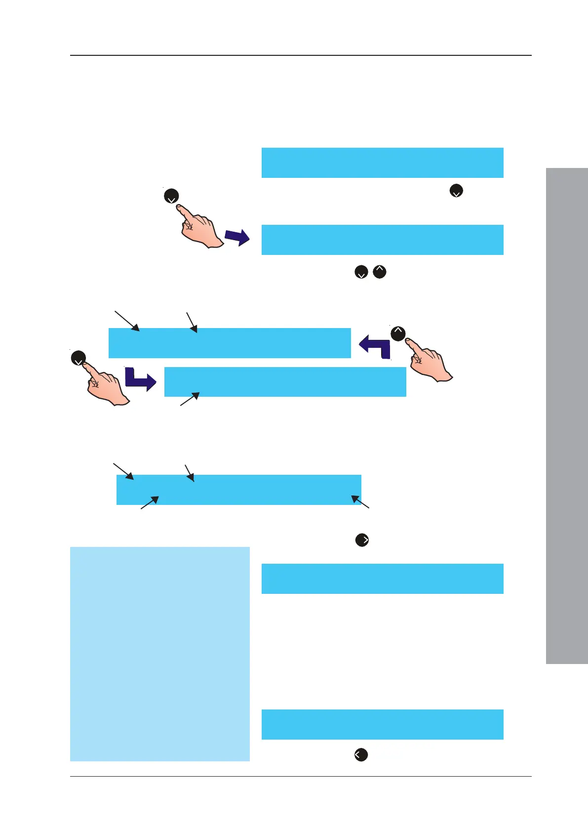
[U0 View] 1:Log 2:Devices 3:Faults
4:Input Events 5:Disabled ¦ : More
[U0 Sensor 02 - OPT] >: Next ¦ : More
PW1:286 2:283 3:285 4:1003 5:0292 <:Exit
[U0 Sensor 03 - OPT] >: Next ¦ : More
PW1:286 2:283 3:285 4:1003 5:0292 <:Exit
Device
Type
Device
Address
Pulse Width Time Periods
2
2
8
[U0 Sensor nn - OPT] >: Next ¦ : More
Level 050% -
〉〉
〉〉
〉 050% -
〉〉
〉〉
〉 050%
[U0 Sensor nn - AAA] >: Next ¦ : More
PW1:286 2:283 3:285 4:1003 5:0292 <:Exit
3 Press the
6
’ button to view additional device
information. For CLIP protocol devices:
Note: Three percentage values are displayed [this is the
device’s alarm level status, e.g. 100% (default) is
equivalent to alarm]. The value on the left is the current
alarm status level. The other percentage values are
historical; the previous two alarm status percentages
are displayed, the one on the left being the more recent.
For OPAL protocol devices, the device data displayed is
for reference purposes only:
4 Press the ‘
4
’ button to return to the View Mode
menu.
CLIP protocol
OPAL protocol
[U0 Sensor 04 - OPT] >: Next ¦ : More
Value: 049, 026, 000, 000, 000, 000; 224
Device
Type
Device
Address
Sub-address values (up to 6 values) Isolator state value
[U0 Sensor 04 - OPT] >: Next ¦ : More
SN.: DA1BFCCB Imp: 31 Rev: 026 Avg: 025, 027
Sub-address Values Explained
Sensors: the first value indicates the
sensor status, i.e fire, pre-alarm, etc. used
by the panel. The next values (before the
semi-colon) are internal to the sensor and,
therefore, are of no concern to the user.
Modules: the first value is interpreted by
the panel as an indication of the module’s
health status. The next values represent
the status, where appropriate, of inputs
and/or output circuits.
In either case, the last value (after the semi-
colon) shows the status of the internal isolator,
if fitted: 224 = isolator closed, 96 = isolator
open. For devices without an internal
isolator this value = 0.
 Loading...


