7 RMA803 Remote Indicator User's Guide Revision 2
2.3 Mounting Remote Indicator
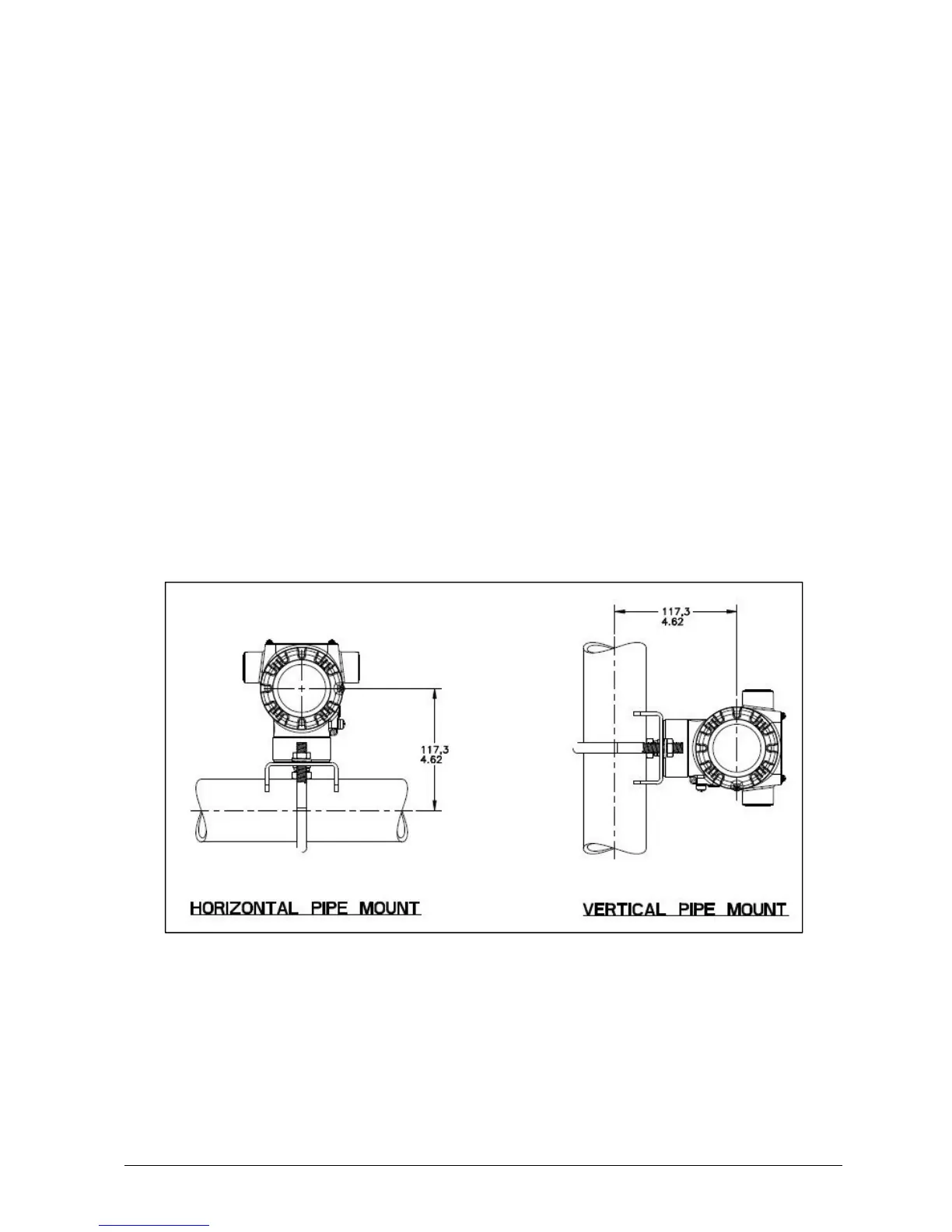
Remote Indicator models can be attached to a two-inch (50.8 millimeter) vertical or horizontal pipe
using Honeywell’s optional pipe mounting bracket. The Remote Indicator can also be wall mounted
using Honeywell’s optional wall mounint bracket as shown in Figure 5.
2.3.1 Mounting Dimensions
Refer to Honeywell drawing number 51455045
*
for detailed electronic housing dimensions. Refer to
Honeywell drawing numbers 32306827
*
for detailed pipe mounting dimensions, 50124813
*
for
Detailed Pipe Angle mounting dimenisons and 32306828
*
for detailed wall mounting dimensions.
Abbreviated overall dimensions are also shown on the Specification Sheets for the Remote Indicator
models. Its assumed that the mounting dimensions have already been considered and the mounting area
can accommodate the Remote Indicator.
2.3.2 Bracket Mounting Procedure
1. Pipe Mount Option -Refer to Figure 6. Align the two mounting holes at the bottom of the
Remote Indicator with the two slots in the mounting bracket and assemble the (2) M8 hex cap
screws, (2) lockwashers and (2) flat washers provided.
2. Rotate the Remote Indicator assembly to the desired position and torque the M8 hex cap screws
to 27,0 Nm/20,0 Lb-ft maximum
* Honeywell drawings can be supplied on request.
Figure 5: Typical Pipe Mounted Installations
 Loading...