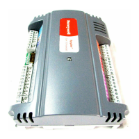
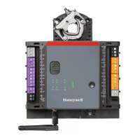
SEC-H-600 SECURITY CONTROLLER
95-7759—07 16
Example Door 1 Wiring
Figure 7 shows a Security Controller wiring schematic for a door with an HID-type reader, normally-closed door contact, normally-
closed exit (REX) device, and a fail-safe DC door strike (normally-closed control).
Fig. 7. Example Door 1 wiring (fail-safe).
Other Terminal Associations
In addition to the pre-allocated I/O for Door Terminal Associations, the Security Controller has the following terminals:
• Supervised Inputs 5 and 6 (SI5, SI6), for general usage. See “Supervised Input,” page 18.
• Relay Outputs 3 and 4, for general usage. See “Auxiliary Relay Output Wiring,” page 21.
• Three unsupervised Digital Inputs (DIs). See “Digital Input,” page 22.
PS+
PS–
BT+
BT–
GND
DC+
AX3
AX1
D1
AX2
D0
NC2
NO1
NC1
NO2
C1
C2
NC3
NO3
C3
NC4
NO4
C4
+
–
CARD
READER
1
GND
SI6
SI1
SI2
SI3
SI5
SI4
GND
GND
Security
Controller
Red
Black
Green
White
optional
optional
optional
Exit Request
Door Contact
HID
Reader
Door
Strike
Strike
Power
Supply

 Loading...
