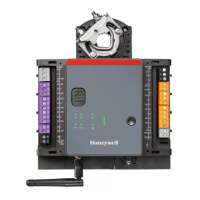
SEC-H-600 SECURITY CONTROLLER
17 95-7759—07
Reader Input
The SEC-H-600 controller has two door reader inputs, each supporting a Wiegand-type 12Vdc reader. Each reader input has a 7-
position connector, on the circuit board labeled as Card Reader 2 and 1 (see Fig. 4 on page 12). Typical wiring is shown below in
Fig. 8. Pinouts for each card reader connector are shown in Table 5.
NOTE: A door wired to a reader input has other I/O points, see “Door Terminal Associations,” page 15.
Fig. 8. Reader wiring to Security Controller.
Reader Wiring Notes
• Mount the reader, referring to the specific manual for that reader for instructions.
• Use shielded, twisted-pair, cabling (Belden #8725 or #8723 or equivalent, as needed) to connect the reader to the Security
Controller. Maximum cable distance is 500 feet (152m).
• Run this cabling from the reader to the Security Controller, bringing it through an appropriate knockout in the enclosure used.
Allow sufficient slack cable for servicing.
• Tie all shield wires together, and connect to the designated grounding point at the enclosure. SeeFig. 5 on page 13.
• Place the appropriate wires in the appropriate screw terminals of the 7-position reader connector. Refer to the pinouts in
Table 5 above for reader input designations. Figure 8 above lists typical wiring colors.
Table 5. Pinouts for Card Reader Inputs
Terminal Terminal Name Terminal Notes Typical cabling colors
DC+ +12Vdc to Reader Always wire these four terminals to the
corresponding reader terminals.
Typically Red wire.
GND Ground Typically Black wire.
D0 Reader Data 0 Typically Green wire.
D1 Reader Data 1 Typically White wire.
AX1 Auxiliary 1 Optional, wire to reader’s Green LED
control
At reader, typically Orange wire.
AX2 Auxiliary 2 Optional, wire to reader’s Red LED control At reader, typically Brown wire.
AX3 Auxiliary 3 Optional, wire to reader’s Beeper control At reader, typically Blue or Yellow
wire.
GND
DC+
AX3
AX1
D1
AX2
D0
CARD
READER
n
Red (+12Vdc)
Black (Ground)
Green (Data 0)
White (Data 1)
optional 1
optional 2
optional 3
Reader
Shields
NOTE: Maximum current rating for
both reader inputs (combined) is:
• Peak current maximum: 0.40A
• Average current maximum:0.30A

 Loading...
