SEC-H-600 SECURITY CONTROLLER
95-7759—07 24
Serial
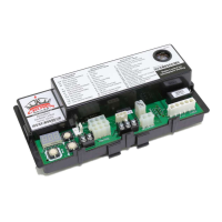
There are two serial ports on the SEC-H-600 base unit. At the bottom of the board (see Fig. 13.), the DB-9 is an RS-232 port
using an DB-9 plug (male) connector. At the ends of the unit, an RS-485 port “passes through” the unit using the lower 3
terminals of the 6-position connectors.
NOTE: A green “receive” LED and yellow “transmit” LED are provided for each serial port. These LEDs are located on the bot-
tom board, next to each port connector (see Fig. 4 on page 12).
There is also a USB port on the top board. However, it is for future use only.
RS-232
An RS-232 serial port using a male DB-9 connector always operates as COM1. You can use standard DB-9 serial cables with this
port. The Security Controller is a serial DTE device, requiring a “null modem” cable for connection to another DTE device, such
as a PC. If connecting the Security Controller to a DCE device (modem, for example), a straight-through cable is used. The table
below provides standard serial DB-9 pinouts.
NOTE: If a modem option card (NPB-MDM) is installed, this port becomes disabled—except if rebooted with the mode jumper
(see Fig. 4 on page 12) in the “Serial Shell” position.
RS-485
An RS-485, optically isolated port is dedicated for communications to security expansion modules (SEC-H-R2R, SEC-H-RIO),
and always operates as COM2. Wiring is not necessary to any modules that directly attach in-line with the Security Controller—
the RS-485 signal passes through the 6-position end connectors.
If modules are not mounted in-line with the Security Controller, wire between the device assemblies using the 6-position end
connector plugs. Use shielded 18-22AWG wiring (refer to the TIA/EIA-485 standard). As shown in Table 6 above, the screw
terminals (from left-to-right) are shield, plus (+), and minus (–).
Wire in a continuous multidrop fashion, meaning “plus to plus,” “minus to minus”, and “shield to shield.” Connect the shield to
earth ground at one end only, such as at the Security Controller. See Fig. 14 on page 25 for example cabling.
Table 6. Serial port (RS-232 and RS-485) pinouts.
Base RS-232 DB-9 Port (COM1) Base RS-485 Port (COM2)
Pinout References Signal DB-9 Plug Pin Pinouts
DCD Data carrier detect 1
RXD Receive data 2
TXD Transmit data 3
DTR Data terminal ready 4
GND Ground 5
DSR Data set ready 6
RTS Request to send 7
CTS Clear to send 8
Not used on the Security Controller 9
DB-9 Plug (male)
1
5
6
9
6-position end connector (male)
S
+
–

 Loading...