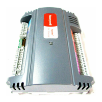
SEC-H-600 SECURITY CONTROLLER
19 95-7759—07
Supervised Input Wiring Notes
• The device monitored by a supervised input should have dry contacts (voltage free) as either a normally-open or normally-
closed type switch. Mount the device per the vendor’s instructions.
• Use shielded, twisted-pair, cabling to connect the device to the Security Controller. Maximum cable distance is 2000 feet
(610m)
• Run this cabling from the device to the Security Controller, bringing it through an appropriate knockout in the enclosure used.
Allow sufficient slack cable for servicing.
• At the device, connect the cable by installing one of the supplied 4-lead EOL resistor packs. Install this resistor pack as close
as possible to the device’s contacts.
Depending on new or old style EOL resistor pack, wire the EOL leads by color. See Fig. 9 on page 18.
—If a new style EOL pack, wire the red lead and either black lead across the monitored contacts, and wire the white lead to
the “SIn” input, and the other black lead to the SI “GND” input.
— If an old style EOL pack, wire the black leads across the contacts, and wire the white lead shown internally connected to
the black lead (common) to the “GND” input, and the other white lead to the “SIn” input. Note you can use a multimeter to
determine which of the two EOL pack white leads are common to one of the black leads.
Insulate the shield wire at the device by taping back or using shrink tubing.
• At the Security Controller, ground shield drain wires at the enclosure. See Fig. 5 on page 13.
• Connect the two conductors from the device’s contacts to the appropriate SIn terminal and adjacent GND terminal. Note that
inputs SI5 and SI6 are available for general usage, while the other SI inputs (SI1–SI4) are reserved for Door 1 and 2 usage.
About Supervised Input States
Although monitoring a digital (two-state) device, each supervised input has four possible states:
• Shorted—A “trouble” state, meaning shorted input—supervision resistors cannot be detected.
• Closed—A “normal” state, meaning contacts closed, with supervision resistor(s) detected.
• Open—A “normal” state, meaning contacts open, with supervision resistor(s) detected.
• Cut—A “trouble” state, meaning an open input—supervision resistors not detected.
Each supervised input tests for the current state using a simple voltage divider, using a (fixed) 1.5K ohm onboard pull-up resistor,
and the resistance (R) value in ohms of the monitored device, where
Input %= R / (R + 1500)
0%–17% = 0 (shorted wires) to 300
17%–50% = 300 to 1500 (Closed)
50%–83% = 1500 to 7500 (Open)
83%–100% = 7500 to infinite (cut wires)

 Loading...
