SmartLine Pressure Transmitter
14 Quick Start Installation Guide December 2016
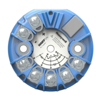
Figure 11: Terminal Block and Grounding Screw location
Note: The right hand terminal is for loop test and is not applicable for the Fieldbus
option.
Wiring Variations
The above procedures are used to connect power to a Transmitter. For loop wiring
and external wiring, detailed drawings are provided for Transmitter installation in
non-intrinsically safe areas and for intrinsically safe loops in hazardous area locations.
This procedure shows the steps for connecting power to the transmitter.
Wiring must comply with local codes, regulations and ordinances. Grounding
may be required to meet various approval body certification, for example CE
conformity. Refer to the SmartLine Transmitter User’s Manual, Documents #
34-ST-25-35 (ST 800) or 34-ST-25-44 (ST 700) for details.

 Loading...


