Smart Temperature Transmitter STT250 – Operator Manual 7
4. BENCH CHECK INSTALLATION/COMMISSIONING
4.1 Unpacking
Unpack the unit and verify the contents are as ordered.
4.2 Equipment
If a bench check is intended, the equipment needed is:
ü an input sensor suitable for the required application or an equivalent calibrator
which can simulate milli-volts, resistance temperature detector, thermocouple or
resistance (ohms) inputs,
ü a nominal 24 Vdc power supply with less than 100 mV peak ripple and able to
supply at least 40 mA,
ü a Smart Field Communicator (SFC) with STT25M or STT25D or HART
Communicator (model 275) with STT25H,
ü connection wiring and 250 ohms resistor,
ü a Digital Voltmeter (DVM) with range covering 0-5 Vdc. If a high speed sampling
DVM is used, a 1 Hz (160 msec.) averaging filter is recommended.
NOTE: If you are going to check calibration using a thermocouple input, ensure
that the cold junction temperature is stabilized. After connecting and powering
up all equipment, including the transmitter, protect the transmitter from air
drafts and allow at least 1 hour before taking readings.
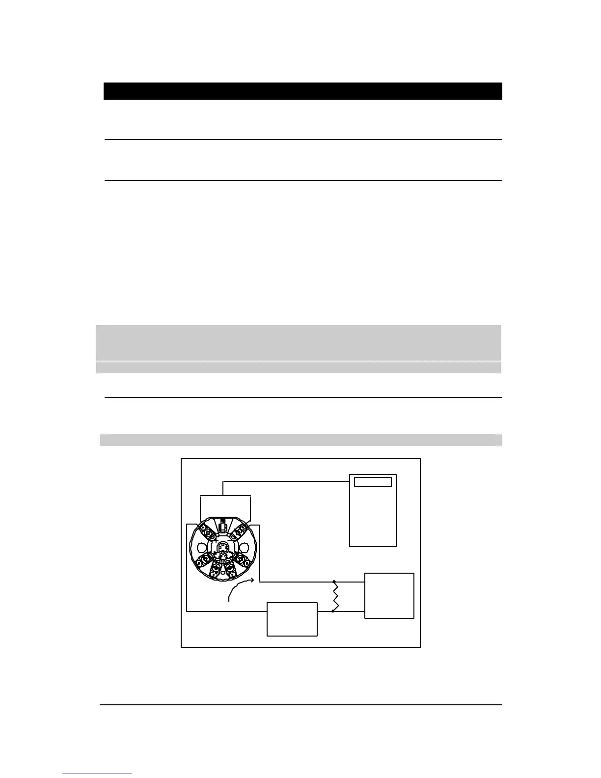
4.3 Installation
Connect the equipment as in Figures 2 and 3. For more detailed wiring drawings, refer
to drawings listed in Section 5.4.
ATTENTION: Do not connect power supply to sensor wiring terminals.
24 Vdc
Power supply
SFC
or
HART
communicator
4-20 mA
DVM
250 ohms
+
-
+
-
Figure 2: Bench Check Wiring Connections

 Loading...


