Do you have a question about the Honeywell T775L Series and is the answer not in the manual?
| Model | T775L Series |
|---|---|
| Input Voltage | 24 VAC |
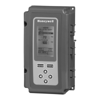
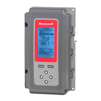
| Display | LCD |
| Enclosure | Plastic |
| Certifications | UL, CE |
| Type | Electronic |
| Input | Thermistor |
| Output | Relay |
| Output Type | Relay |
| Control Mode | On/Off |
| Communication | Optional |
| Humidity Range | 0% to 95% RH |
Provides essential safety and procedural instructions for installing the T775L controller.
Describes how to access and make wiring connections for the T775L controller and its components.
Explains how to calibrate temperature sensors to compensate for wire length resistance loss.
Explains control loops, setpoint, and differential settings for heating and cooling modes.
Guides through changing factory defaults for sensors, outputs, reset, and scheduling.
Configures settings for Sensor A, including units, calibration, and labeling.
Sets the desired temperature setpoint for loops or relays, defining the target operating temperature.
Guides through enabling the Reset feature in Setup mode, starting with Loop 1.
Configures Loop 2 parameters including setpoint offset, throttling range, and heat/cool mode.
Guides on how to create or change a schedule by enabling scheduling and setting options.
Explains error codes (EEPROM Failure) and diagnostic messages for sensor issues (Open/Shorted, Out of Range).
Details electrical power, operating temperature, and relay contact output specifications.