Page 14 Auxiliary Connections
Auxiliary Connections
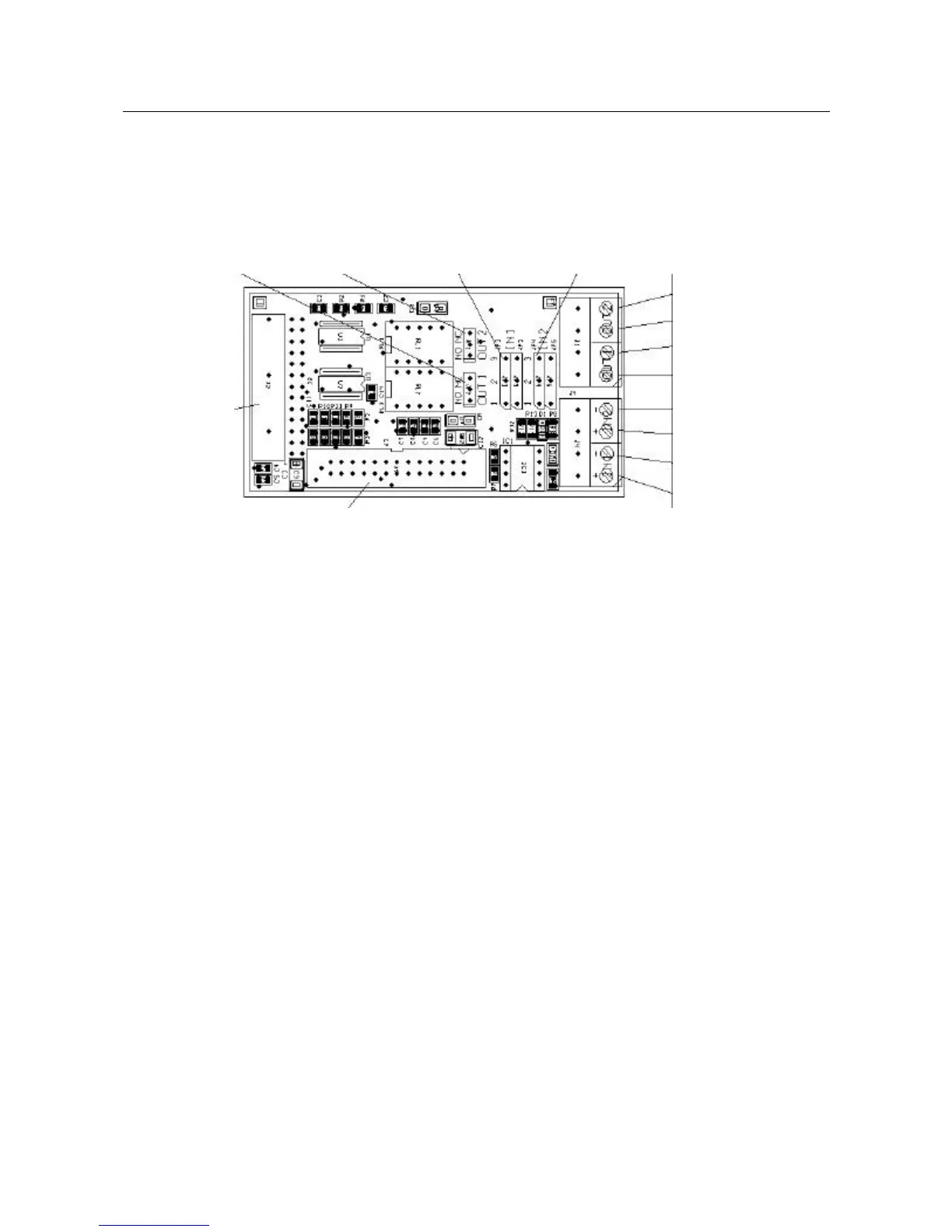
The I/O plug-in board features a connector that includes two opto-coupled
inputs and two relay outputs, as illustrated in Figure 10.
jumper jumper jumpers jumpers
relay 1 relay 2 input 1 input 2
mother
board
relay output 1
relay output 1
relay output 2
relay output 2
input 1 -
input 1 +
input 2 -
input 2 +
Connection to LCD control board
Figure 10: Auxiliary connections
Note: When the cables go externally, shielded cables must be used. The
cable’s shield must be connected to ground connector
You can define the operational mode of each relay by positioning the
appropriate jumpers as follows:
• Jumper «OUT1» between 12 (NO) for relay 1 normally open
• Jumper «OUT1» between 23 (NC) for relay 1 normally closed
• Jumper «OUT2» between 12 (NO) for relay 2 normally open
• Jumper «OUT2» between 23 (NC) for relay 2 normally closed
You can define the operational mode of each input by positioning the
appropriate jumpers as follows:
• Jumpers «IN1» between 12 for input 1 on dry contact
• Jumpers «IN1» between 23 for input 1 opto-coupled
• Jumpers «IN2» between 12 for input 2 on dry contact
• Jumpers «IN2» between 23 for input 2 opto-coupled
 Loading...